
Method and apparatus for reducing NOx emissions

Inactive Publication Date: 2005-11-17
DELPHI TECH INC
View PDF11 Cites 113 Cited by
  • Summary
  • Abstract
  • Description
  • Claims
  • Application Information

AI Technical Summary

Benefits of technology

[0006] Disclosed herein are reductant pumps, reductant systems, and methods for using reductant systems. In one embodiment, a reductant system, comprises: a high pressure reductant pump in operable communication with a power source, wherein the reductant pum

Problems solved by technology

Internal combustion engines emit undesirable pollutants in their exhaust stream.
However, the extra oxygen tends to inhibit the removal of NOx.
(It is noted that stoichiometry (i.e., an air / fuel ratio of nearly balanced stoichiometry for combustion) changes based upon fuel composition, i.e., gasoline, diesel, alcohol, mixtures, etc.) However, in the case of an exhaust gas having a relatively high oxygen concentration, such as those discharged from diesel engines and those discharged from gasoline engines operated lean of stoichiometry, efficient removal of NOx cannot be achieved with the above-described devices.
Whereas homogeneous charge engines are able to utilize passive self-contained catalytic reduction techniques as exemplified by the three-way catalyst to control emissions of HC, CO, and NOx, so-called lean-burn engines as exemplified by the compression ignition engine, may have high oxygen content in the exhaust which renders conventional catalysis ineffective.
Although various techniques of urea introduction to an exhaust system have been tried, many of these techniques require complex equipment and / or controls.

Method used


Image

  • Method and apparatus for reducing NOx emissions
  • Method and apparatus for reducing NOx emissions
  • Method and apparatus for reducing NOx emissions

Examples


Embodiment Construction

[0018] The use of the terms first, second, etc. do not denote any order or importance, but rather the terms first, second, etc. are used to distinguish one element from another, and the terms “a” and “an” herein do not denote a limitation of quantity, but rather denote the presence of at least one of the referenced item. It is noted that this application is described in relation to use in relation to an exhaust stream. This exhaust stream can be any exhaust stream, e.g., a vehicle exhaust stream (such as an automobile, passenger vehicle, truck, or the like), a cogenerator exhaust stream, or the like.

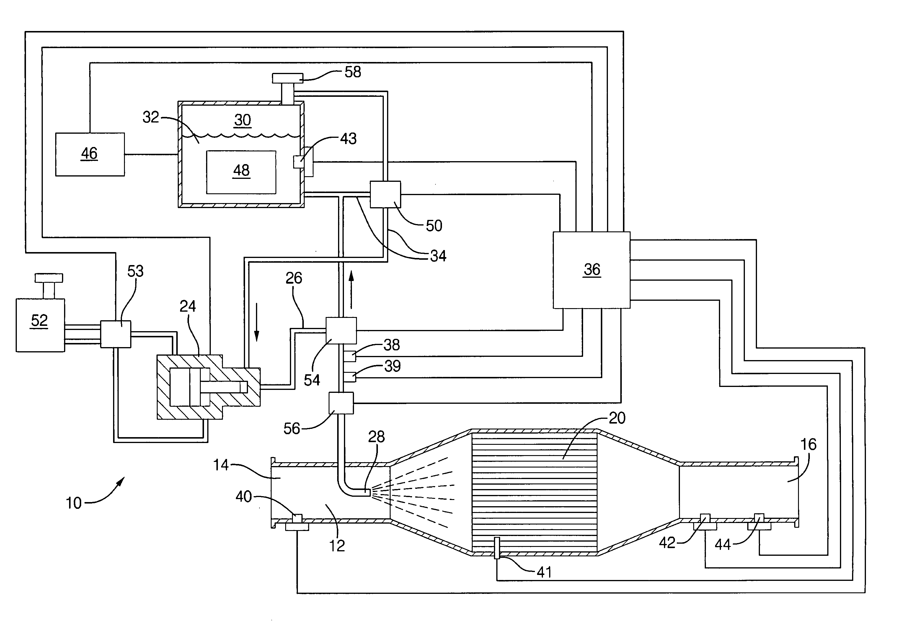
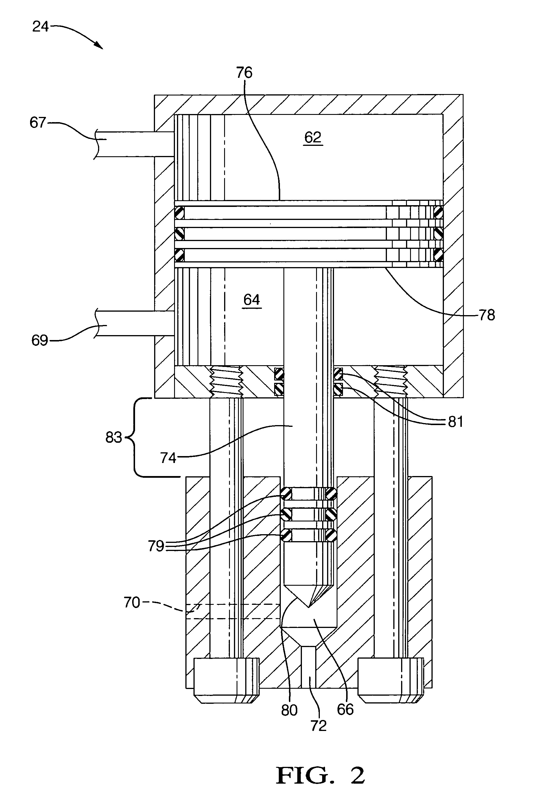
[0019] Disclosed herein is a reductant system, e.g., for injecting reductant (e.g., urea, ammonia, hydrocarbons, or the like) upstream of or into an exhaust treatment device, such as for the removal of NOx from an exhaust stream. Referring now to FIG. 1, a schematic illustration of a system 10 is shown. The system 10 can include an exhaust system of a vehicle as well as parts of other v...


PUM


Abstract

In one embodiment, a reductant system comprises: a high pressure reductant pump in operable communication with a power source, wherein the reductant pump comprises a reductant chamber and is capable of pressurizing reductant to a pressure of greater than or equal to 500 psi; a reductant reservoir in fluid communication with the reductant chamber; and an atomizer in fluid communication the reductant chamber. In another embodiment, the reductant system comprises: a reductant pump; system pump in operable communication the reductant pump, a reductant reservoir in fluid communication with the reductant chamber, and an atomizer in fluid communication the reductant chamber. The system pump is configured to provide motive power via a pressurized fluid to the reductant pump, and the system pump is fluidly isolated from a reductant chamber in the reductant pump.

Description

TECHNICAL FIELD [0001] This disclosure relates generally to a method and system for reducing nitrogen oxides (NOx), and more specifically relates to a method and system for reducing NOx emissions from the exhaust gas feedstream. BACKGROUND [0002] Internal combustion engines emit undesirable pollutants in their exhaust stream. Those pollutants include NOx such as nitrogen monoxide, nitrogen dioxide. NOx is generated from internal combustion engines such as diesel engines, and large combustion apparatuses such as cogenerators. Accordingly, exhaust systems are coupled to the engine to limit and / or remove the pollutants from the exhaust system. Technologies have been and continue to be developed to attenuate these emissions. [0003] NOx is cleaned from exhaust gases of internal combustion engines through the use of catalysts. In addition to removing NOx, these catalysts also remove unburned hydrocarbons (HC) and carbon monoxide (CO). When the engine is operated with a lean air / fuel ratio...

Claims


Application Information

Patent Timeline
IPC IPC(8): F01N3/00F01N3/10F01N3/20F01N9/00
CPCF01N3/2066F01N3/36F01N9/00F01N2430/04F01N2560/021F01N2560/026Y02T10/24F01N2610/02F01N2610/1433F01N2610/146F01N2900/08F01N2900/12Y02T10/47F01N2560/06Y02T10/12Y02T10/40
Inventor LECEA, OSCAR A.RALPH, JOSEPH G.GOULETTE, DAVID A.
Owner DELPHI TECH INC
Learn More