Reversible rotatable cutting and ironing board combination

Inactive Publication Date: 2005-11-17
YAMIN PATRICIA JANE
View PDF13 Cites 14 Cited by
  • Summary
  • Abstract
  • Description
  • Claims
  • Application Information

AI Technical Summary

Benefits of technology

[0017] Yet another object of the present invention is to provide a rotatable turntable structure comprising a combined cutting plate and an ironing board which are rotatable relative to each other so as to enable the cut

Problems solved by technology

Although the foregoing structures each incorporate surfaces for cutting and further surfaces for pressing or ironing, these structures are ess

Method used


Image

  • Reversible rotatable cutting and ironing board combination
  • Reversible rotatable cutting and ironing board combination
  • Reversible rotatable cutting and ironing board combination

Examples


Embodiment Construction

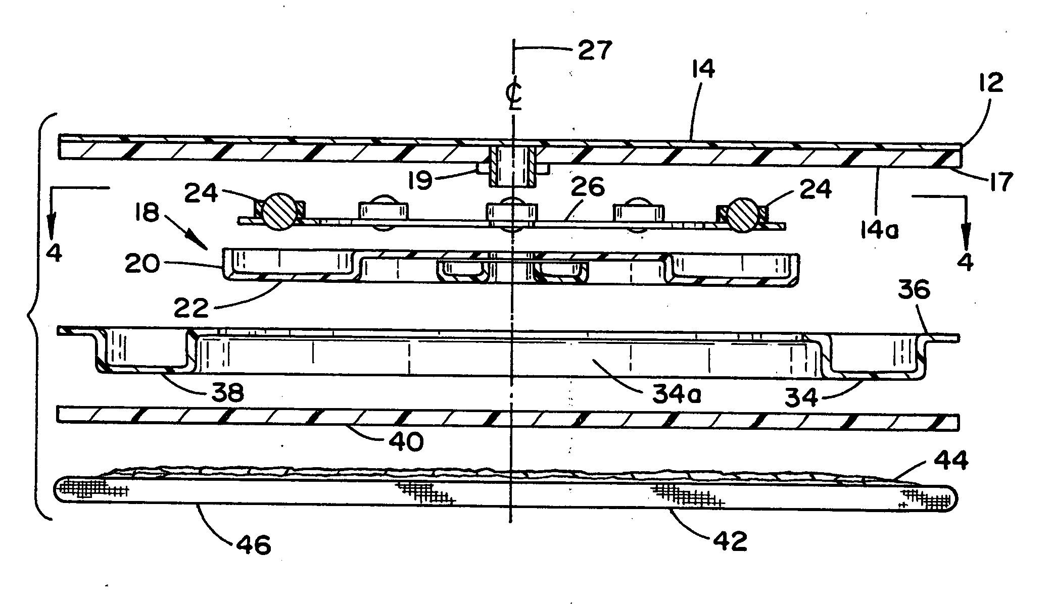
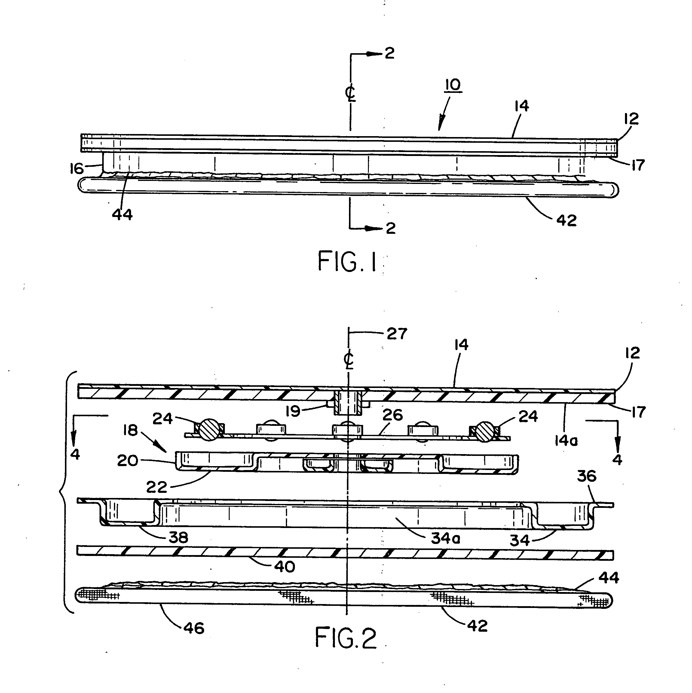
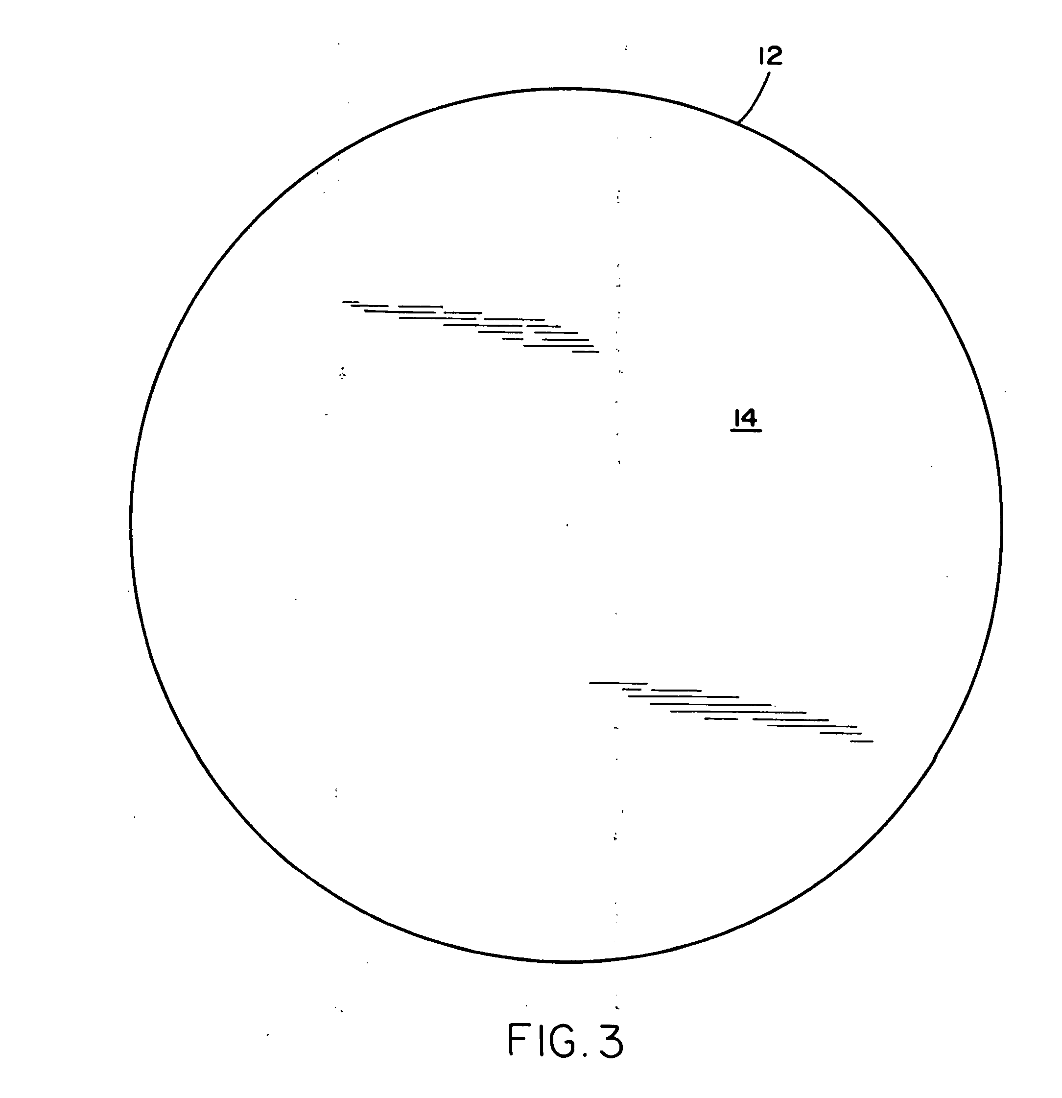
[0024] Referring in detail to the drawings, particularly FIG. 1, there is illustrated a turntable assembly 10 constituted of a circular disk member 12 having a cutting surface 14 as also shown in FIG. 3 of the drawings, and which is constituted of a die cut and hot stamp decorated top cutting board of a rigid plastic material. The cutting surface 14 may be of a so-called “self-healing nature” when subjected to cutting action.

[0025] Laminated thereto is a stock race assembly 16 comprising a disk-shaped plate member 17 of rigid plastic, which is attached to the opposite surface 14a of member 12 by gluing as is well known in the art, and which on the opposite side thereof has a grommet and sleeve member 19 rotatably connected to a stock race unit 18 constituted of plastic material. As shown in FIG. 2, in the exploded transverse sectional view thereof, taken along line 2-2 in FIG. 2, the stock race includes a first member 20 of a molded plastic ring-shaped configuration, having an annu...


PUM


Abstract

A reversible combination cutting and ironing board, and more particularly, pertains to a turntable structure incorporating a disk-shaped plate having a cutting surface on one side thereof, and a second disk-shaped plate forming an ironing board on the opposite side, which are rotatable about a transverse center axis relative to each other.

Description

BACKROUND OF THE INVENTION [0001] 1. Field of the Invention [0002] The present invention relates to a reversible combination cutting and ironing board, and more particularly, pertains to a turntable structure incorporating a disk-shaped plate having a cutting surface on one side thereof, and a second disk-shaped plate forming an ironing board on the opposite side, which are rotatable about a transverse center axis relative to each other. [0003] In the field of quilting wherein numerous and the most diverse types of designs and patterns are employed for the purpose of forming quilts of the most decorative natures, pieces of fabric are cut into appropriate sections or squares by employing templates which are maintained in position on the fabric, the latter of which is positioned on a mat or planar cutting surface. Heretofore, in order to provide the appropriate sections of fabric being cut with a high degree of accuracy, through the intermediary of templates and the application of cut...

Claims


Application Information

Patent Timeline
IPC IPC(8): A47B11/00B26D7/20D06F81/00D06H7/00
CPCB26D7/20D06H7/00D06F81/00
Inventor YAMIN, PATRICIA JANE
Owner YAMIN PATRICIA JANE
Why Eureka
Try Eureka