
Methods and devices for locating and uniquely provisioning RFID devices

a technology of radio frequency identification and uniquely provisioning, applied in the field of radio frequency identification technology, can solve the problems of preventing the realization of this theory, wasting rf engineers considerable time and energy, and bar codes have drawbacks, and achieve the effect of easy identification of rfid devices

Inactive Publication Date: 2005-11-17
CISCO TECH INC
View PDF44 Cites 60 Cited by
  • Summary
  • Abstract
  • Description
  • Claims
  • Application Information

AI Technical Summary

Benefits of technology

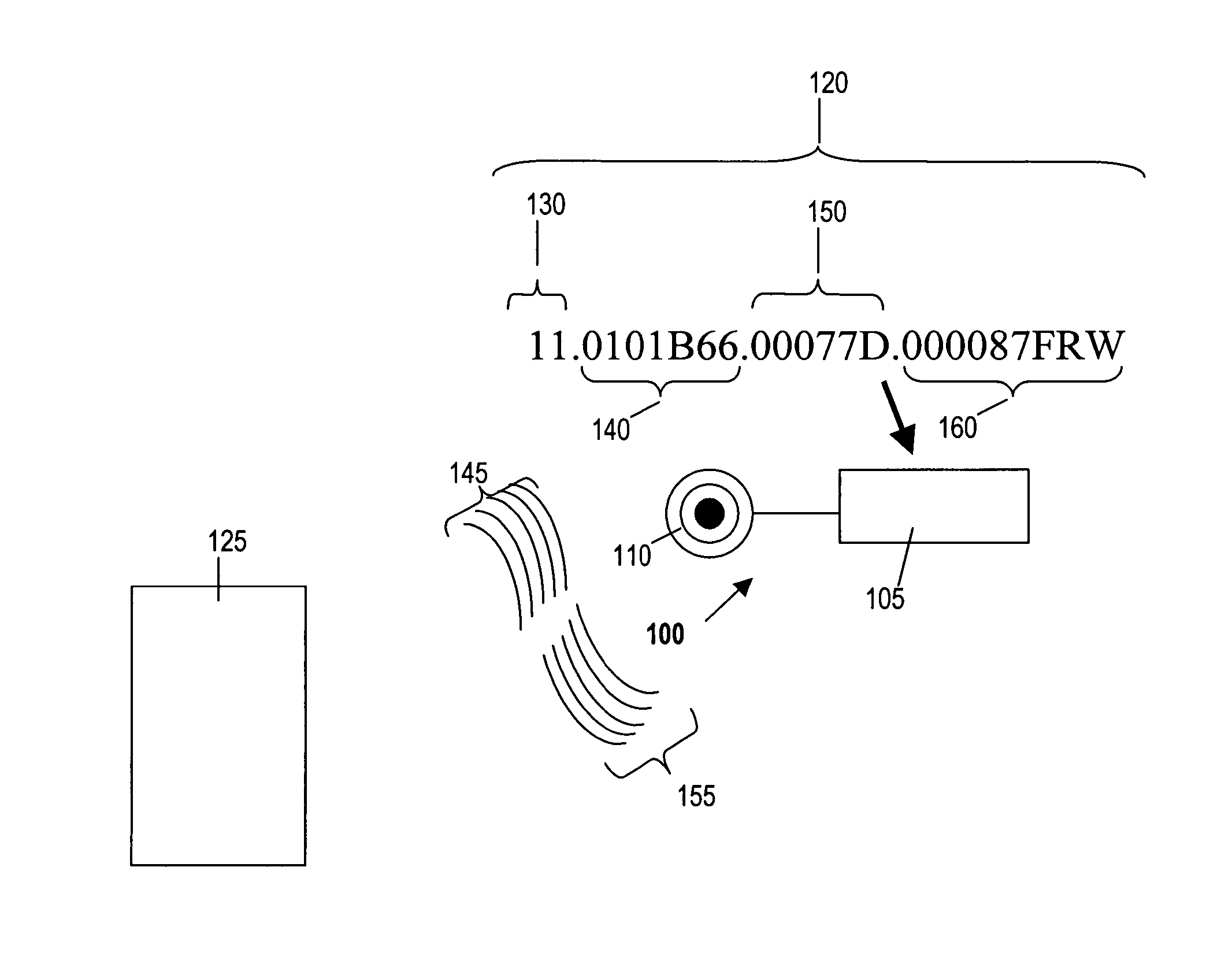
[0019] In order to secure the DHCPFORCERENEW command, some implementations provide for a cached secret to be hashed with a client EPC that is included with the DHCPREQUEST from the RFID device and the response from the DHCP server. Some implementations employ Domain Name Service (“DNS”) and dynamic DNS (“DDNS”) to allow easy identification of RFID devices.

Problems solved by technology

However, bar codes have some drawbacks.
However, various difficulties have prevented this theory from being realized.
One problem that has required considerable time and energy from RF engineers is the development of lower-cost RFID tags with acceptable performance levels.
Unfortunately, the materials used in inductively-coupled RFID tags make them too expensive for widespread use: a passive button tag costs approximately $1 and a battery-powered read / write tag may cost $100 or more.
However, conventional capacitively-coupled RFID tags have a very limited range.
In part because of the significant efforts that have been expended in solving the foregoing problems, prior art systems and methods for networking RFID devices are rather primitive.
Device provisioning for prior art RFID devices is not automatic, but instead requires a time-consuming process for configuring each individual device.
Prior art RFID devices and systems are not suitable for large-scale deployment of networks of RFID devices.
Moreover, many RFID devices are deployed in a hostile industrial environment (such as a warehouse or factory) by relatively unskilled “IT” personnel.
In practice, RFID devices are moved if another device is damaged or not functioning.
However, if an RFID device is moved, prior art systems do not know to what location the RFID device has been moved.

Method used


Image

  • Methods and devices for locating and uniquely provisioning RFID devices
  • Methods and devices for locating and uniquely provisioning RFID devices
  • Methods and devices for locating and uniquely provisioning RFID devices

Examples


Embodiment Construction

[0041] In this application, numerous specific details are set forth in order to provide a thorough understanding of the present invention. It will be obvious, however, to one skilled in the art, that the present invention may be practiced without some or all of these specific details. In other instances, well known process steps have not been described in detail in order not to obscure the present invention.

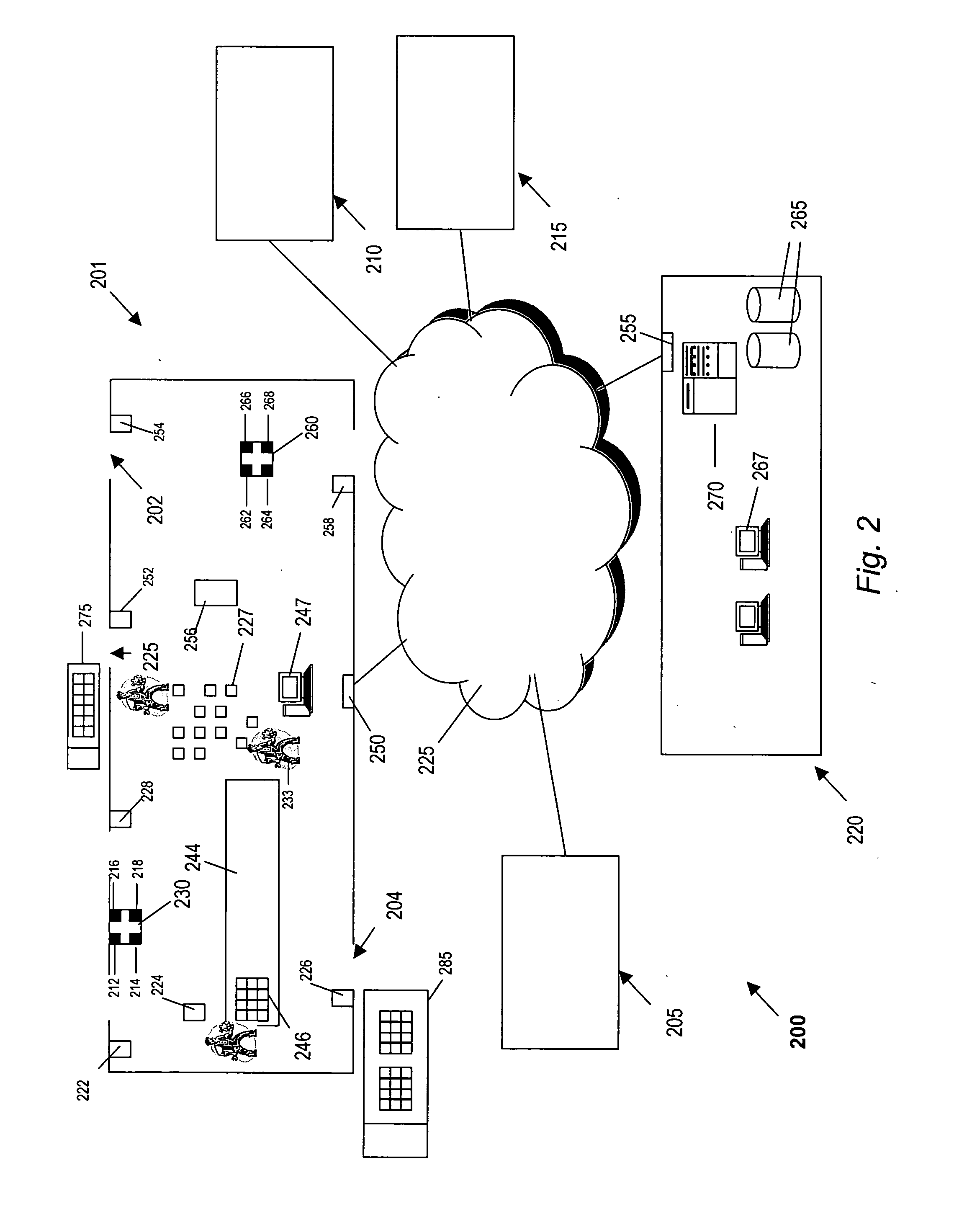
[0042] Although the present invention involves methods and devices for identifying and provisioning individual RFID devices in a network, many aspects of the present invention can be applied to identifying and provisioning other types of devices in a network. Similarly, although much of the discussion herein applies to implementations using the DHCP protocol, the present invention is not protocol-specific and may be used, for example, in implementations using UPnP, 802.1ab or similar discovery protocols. Likewise, while the implementations described herein refer to exemplary DHC...


PUM


Abstract

Methods and devices are provided for identifying, locating and provisioning individual RFID devices in a network. According to some implementations of the invention, a combination of EPC code information and existing networking standards form the basis of identifying and provisioning methods. For example, MAC address information and EPC information can be combined to identify a particular device and its location in a network. For implementations using the Dynamic Host Configuration Protocol (“DHCP”), DHCP Options may be used to pass provisioning information. Some implementations employ Domain Name Service (“DNS”) and dynamic DNS (“DDNS”) to allow easy identification of RFID devices.

Description

CROSS-REFERENCES TO RELATED APPLICATIONS [0001] This application claims priority to U.S. Provisional Patent Application No. ______, (attorney docket number CISCP378P), entitled “Methods and Devices for Uniquely Provisioning RFID Devices” and filed on May 13, 2004, which is hereby incorporated by reference for all purposes. This application is related to U.S. patent application Ser. No. ______, (attorney docket number CISCP376), entitled “Methods and Devices for Uniquely Provisioning RFID Devices” and filed on ______, and is also related to U.S. patent application Ser. No. ______, (attorney docket number CISCP378), entitled “Methods and Devices for Assigning RFID Device Personality” and filed on ______, both of which are hereby incorporated by reference for all purposes.BACKGROUND OF THE INVENTION [0002] 1. Field of the Invention [0003] The present invention relates to radio frequency identification (“RFID”) technology. More particularly, the present invention relates to provisioning...

Claims


Application Information

Patent Timeline
IPC IPC(8): G01S13/82G06F17/00
CPCG01S13/825
Inventor HOWARTH, ARTHUR G.DROMS, RALPHSAVILLE, ROLANDKREEGER, LAWRENCEWIBORG, CHRISTOPHERBUTANEY, VIKASSINGHAL, RAJIV
Owner CISCO TECH INC
Learn More