Cryogenic clamp-on pipe anchor

Active Publication Date: 2005-11-17
RILCO MFG
View PDF11 Cites 31 Cited by
  • Summary
  • Abstract
  • Description
  • Claims
  • Application Information

AI Technical Summary

Benefits of technology

[0007] The present invention provides a clamp-on anchor that can be assembled to a pipeline in the field that posi

Problems solved by technology

Prior art clamp-on anchor products did not address the issues of pipe rotation and aligning the top and bottom cradles.
The housing sections too

Method used


Image

  • Cryogenic clamp-on pipe anchor
  • Cryogenic clamp-on pipe anchor
  • Cryogenic clamp-on pipe anchor

Examples


Embodiment Construction

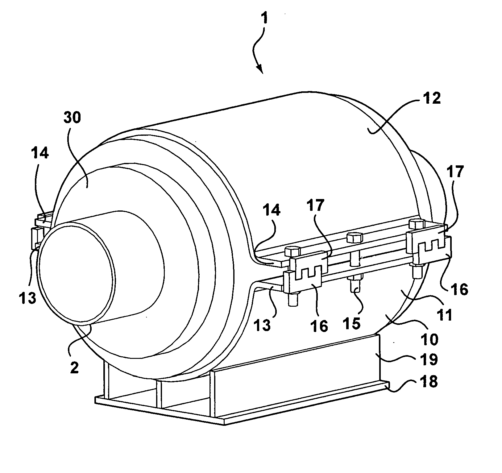
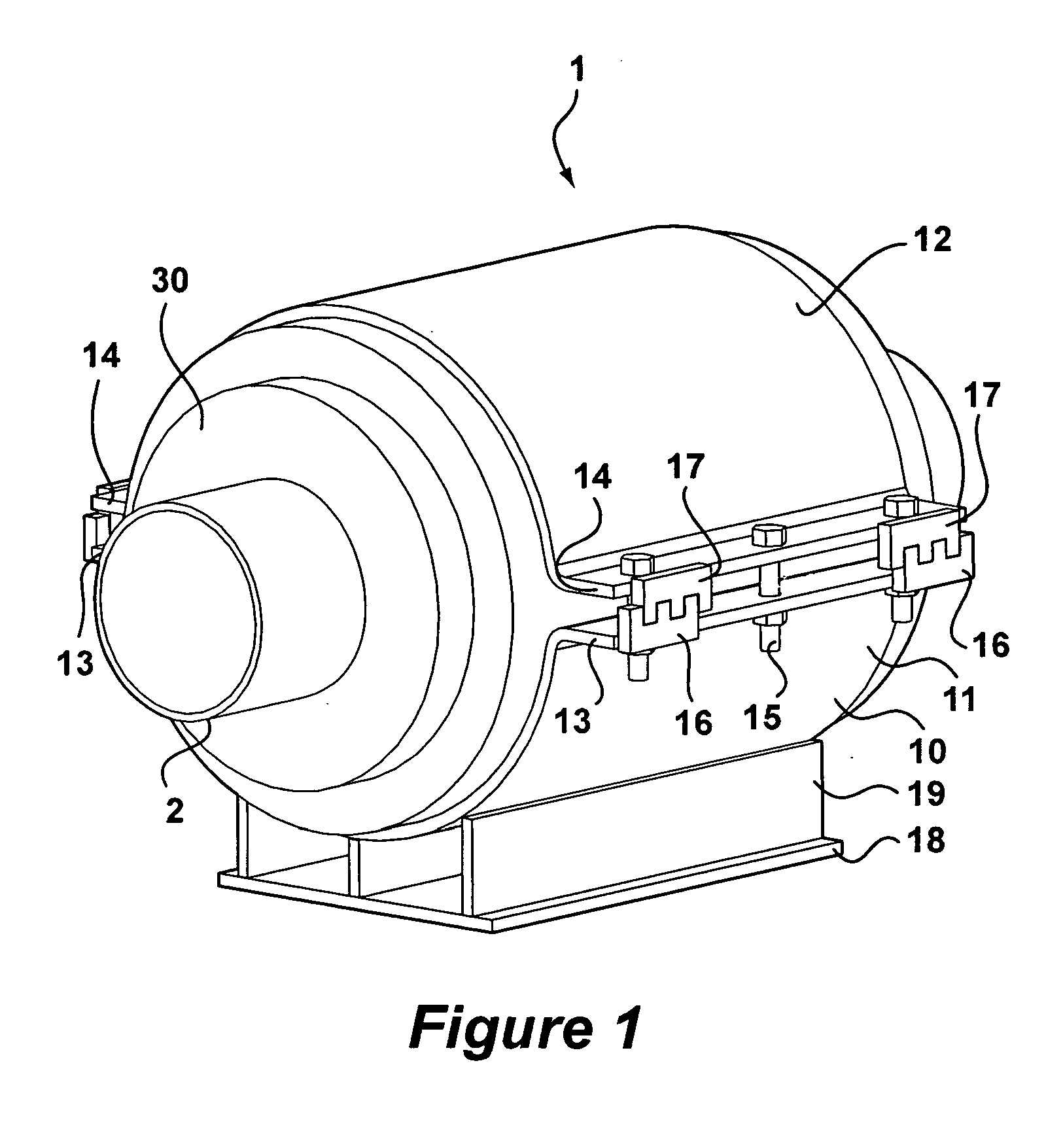
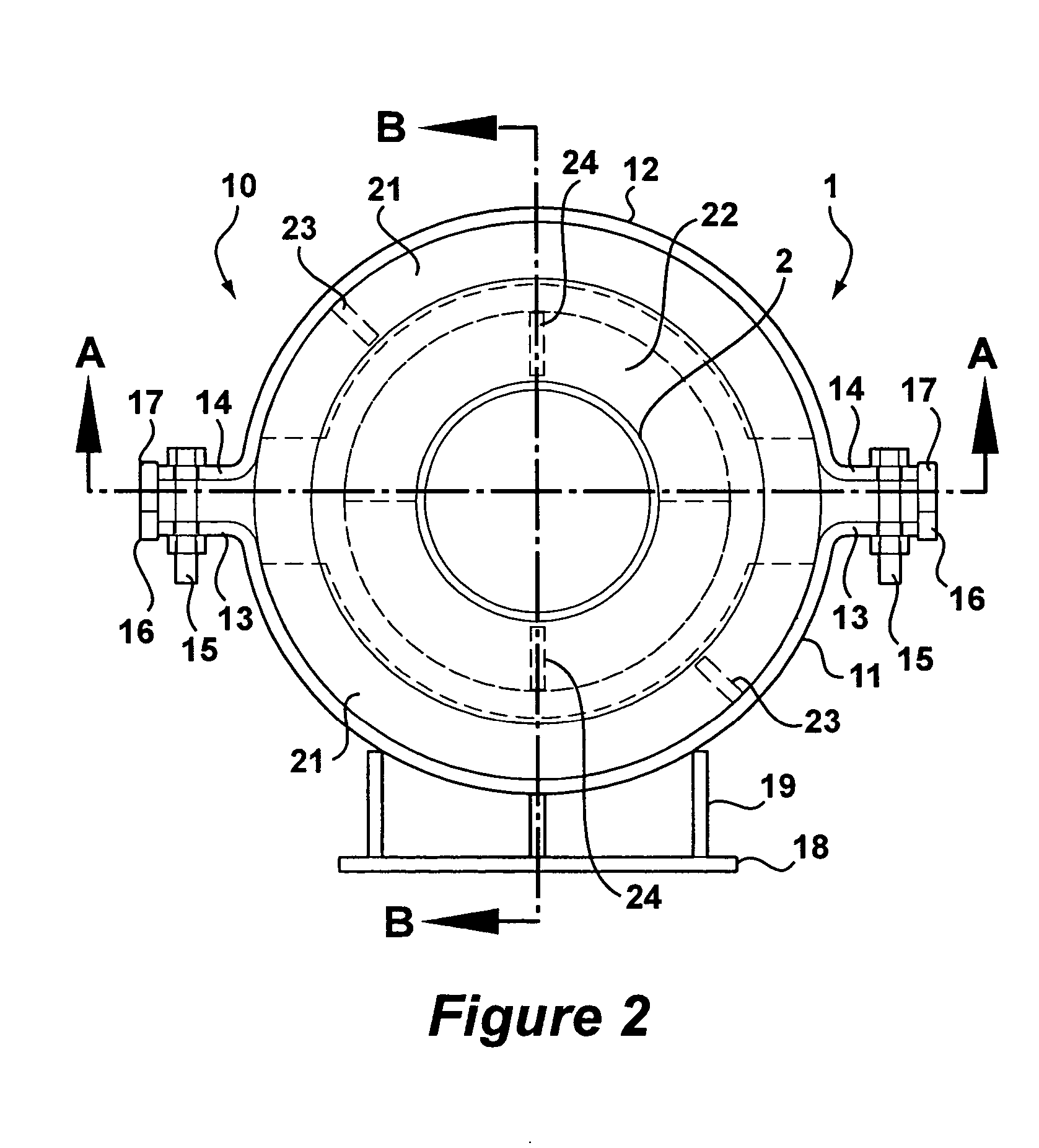
[0028] Referring to FIG. 1, a perspective view of an anchor of the present invention as shown. The anchor 1 generally consist of a housing 10, a system of lugs 20 and insulation material 30, all of which surround and support a pipe section 2 (lugs 20 not shown). The housing 10 has a base cradle 11 and a top cradle 12. Each of these cradles are semi-circular in cross section and connect with each other to form a completely cylindrical housing structure that encircles the insulation material 30 and the pipe section 2. The base cradle 11 has a base flange or ear 13 on each side, which extends perpendicularly outward from the half-cylinder. Similarly, the top cradle 12 has a top flange or ear 14 on each side which extend perpendicularly outward from the half-cylinder. When the base cradle 11 and top cradle 12 are assembled to form a complete cylinder, the base flanges 13 are positioned adjacent the top flanges 14. A plurality of bolts 15 extend through holes in the flanges 13 and 14 to ...


PUM


Abstract

A pipe anchor having: a base cradle with a lug; a top cradle with a lug and secured to the base cradle so as to encircle a pipe within the base cradle and the top cradle; a locking mechanism with opposite mating components attached to the base cradle and the top cradle; at least one lug attached to the pipe; and insulation material filling a space between the pipe and the cradles, wherein the insulation material engages the at least one lug of the pipe and the lugs of the cradles.

Description

BACKGROUND OF THE INVENTION [0001] 1. Field of the Invention [0002] This invention relates to insulated pipes. In particular, this invention relates to insulated pipe anchors or restraints for insulated pipes. [0003] 2. Description of the Prior Art [0004] Typically, prior art cryogenic pipe anchors are pre-assembled in a factory and delivered to the field with insulated pipe sections already contained within the anchor. The anchor housings are configured as a unitary cylindrical housing that encircles a pipe section and slipped over the end of a pipe section. With the housing and pipe section coaxially aligned, insulation material is injected into the annulus defined between the housing and the pipe section. [0005] Other prior art anchors may be clamped onto the pipeline in the field. These clamp-on anchors have multi-section housings that are less stable than the unitary housings provided with pre-assembled housings. Prior art clamp-on anchor products did not address the issues of ...

Claims


Application Information

Patent Timeline
IPC IPC(8): F16L1/06F16L1/20F16L3/00F16L59/12
CPCF16L1/06F16L1/20Y10T403/5781F16L59/135F16L59/123
Inventor ZAGORSKI, KENNETH L.DONOGHUE, JOSEPHBOCK, MICHAEL
Owner RILCO MFG
Why Eureka
Try Eureka