Methods for processing dispersive acoustic waveforms

a technology of dispersed acoustic waveforms and methods, applied in the field of methods, can solve the problems of difficult to determine exact values, complicated calculation of formation slowness, and limitations of dstc processing, so as to minimize the possibility of model error in acoustic data, reduce the size of error bars, and minimize the effect of model error

Active Publication Date: 2005-11-17
SCHLUMBERGER TECH CORP
View PDF7 Cites 36 Cited by
  • Summary
  • Abstract
  • Description
  • Claims
  • Application Information

AI Technical Summary

Benefits of technology

[0011] The present invention provides methods to minimize the possibility of error in acoustic data caused by the presence of the tool in the borehole and other uncertainties in the model parameters. The present invention provides a method for processing acoustic data using DSTC processing that comprises calculating dispersion sensitivity and implementing a dynamic processing frequency band to minimize the effects of model error. The method further comprises determining sensitivity limits or “cut-offs” in the received acoustic data for various parameters, including tool presence in the borehole. One such limit on the useful frequency band for processing is established by the realization that the sensitivity of the flexural mode arrivals depends on the frequency of the transmitted signal. Another embodiment of the present invention comprises an iterative process at each depth level wherein a first slowness is estimated using parameters assuming a homogenous isotropic model, and then semblance processing is iteratively repeated until a stop criteria is satisfied. Examples of stop criteria include a decreased error bar size, a minimized change in slowness between iterations, or a coherence (mean or peak) that decreases below a threshold.

Problems solved by technology

Calculating the formation slowness is complex however as many different acoustic types of signals are received in response to a transmitted signal.
Although robust and useful, DSTC processing has limitations.
These parameters need to be considered but their exact values may be difficult to determine.
The lack of precise values for the parameters means that the final slowness estimation will also include some degree of uncertainty.
Furthermore, these can vary throughout the borehole logging, making it inaccurate to apply a uniform value or correction throughout a logged interval.

Method used


Image

  • Methods for processing dispersive acoustic waveforms
  • Methods for processing dispersive acoustic waveforms
  • Methods for processing dispersive acoustic waveforms

Examples


Embodiment Construction

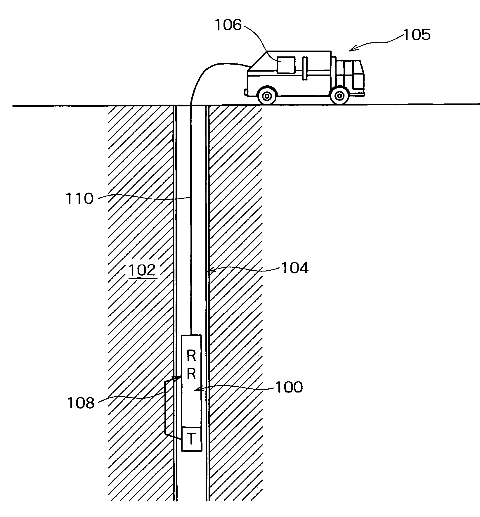
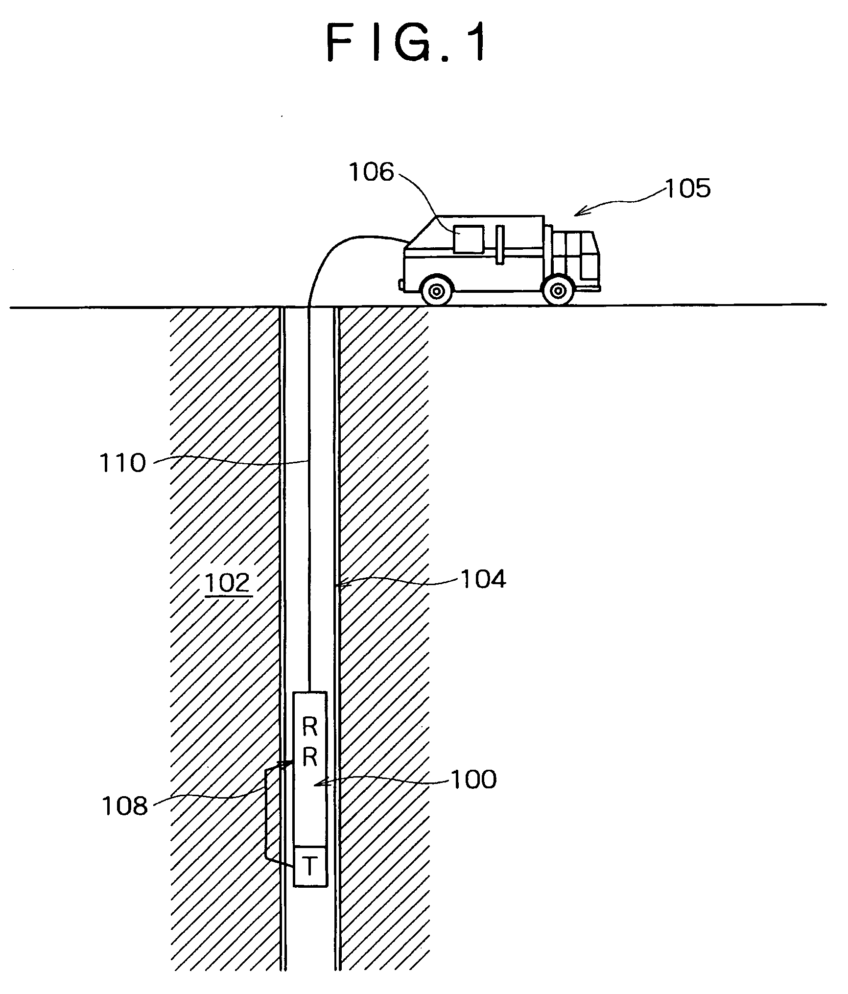
[0023] Turning now to the figures, and in particular to FIG. 1, an acoustic tool (100) is shown adjacent to a homogeneous formation (102). The homogeneous formation (102) is cased with a casing (104). The acoustic tool (100) includes at least 3 transducers consisting of at least one transmitter (T), and at least one receiver (R). In the present embodiment there are two receivers (R) and one transmitter (T), however, many more receivers (R) and transmitters (T) may also be used. The one transmitter (T), two receiver (R) arrangement shown is exemplary in nature and there may be a full array of receivers and / or transmitters, or a single transmitter (T) and receiver (R). The receivers (R) and transmitter (T) are coupled to a computer processor (106) for collecting and processing data from the acoustic tool (100). Also shown is a wave ray path (108) representing a path for a compressional wave caused by activation of the transmitter (T). The receivers (R) may be of different types, inclu...


PUM


Abstract

A method for processing acoustic data comprising applying a dynamic filter band. The method and apparatus may be particularly adapted to processing sonic data to measure formation slowness in a borehole.

Description

FIELD OF THE INVENTION [0001] The present invention relates generally to methods and apparatus for detecting, removing and / or isolating signals from acoustic waveform data. More particularly, it relates to methods for processing data acquired from sonic borehole logging. BACKGROUND OF THE INVENTION [0002] Acoustic tools are useful in providing a large range of information regarding formation and borehole parameters adjacent the tools. A primary use of acoustic borehole measurements is for estimating compressional and / or shear wave formation slowness. Formation slowness is not measured directly but rather is determined from the various acoustic waveforms received by the receivers. Formation slowness is often measured by placing an array of sensors in a sonde in a borehole, the array including at least one transmitter and at least one receiver; transmitting an acoustic signal from the transmitter; receiving the acoustic signal with the receiver; and calculating the formation slowness ...

Claims


Application Information

Patent Timeline
Patent Type & Authority Applications(United States)
IPC IPC(8): G01V1/36
CPCG01V2210/54G01V1/36G01V1/28G01V1/48
Inventor SAIKI, YOSHIYUKISKELTON, OLIVERPABON, JAHIRSINHA, BIKASH K.
Owner SCHLUMBERGER TECH CORP
Why Eureka
Try Eureka