
Method and device for compacting the ballast bed of a track

a ballast bed and track technology, applied in the direction of track superstructure, roads, constructions, etc., can solve the problems of poor visibility of the lifting device from the track tamping cabin, the inability to use roller pincers in switches, and the considerable additional configuration cost, so as to achieve the effect of reducing the possibility of errors and increasing the working speed

Active Publication Date: 2017-11-16
HP3 REAL GMBH
View PDF11 Cites 7 Cited by
  • Summary
  • Abstract
  • Description
  • Claims
  • Application Information

AI Technical Summary

Benefits of technology

The invention provides a method for automatically controlling the roller pincers and lifting hook of a switch tamping machine to increase working speed and minimize errors. The position of switch components is detected and stored in a database, which is used to automatically displaced the lifting and lining device along the track to access a suitable point of attack for the lifting and lining tool. The suitable tool is selected based on the measured values of the switch component measuring system. This automatic control of the roller pincers and lifting hook compensates for the adverse view and increases the working speed. A video system can also be used for monitoring the roller pincers and lifting hook.

Problems solved by technology

A use of the roller pincers is often not possible in switches due to the crossing rails and in the cross frog.
There is poor visibility of the lifting device from the track tamping cabin because the tamping units block the view.
The disadvantage of providing two working cabins lies in the considerable additional expense for the configuration, i.e. two cabins, two control devices, additional weight and increased need for space.
Video cameras can replace spatial vision only to an inadequate extent.

Method used


Image

  • Method and device for compacting the ballast bed of a track
  • Method and device for compacting the ballast bed of a track
  • Method and device for compacting the ballast bed of a track

Examples


Embodiment Construction

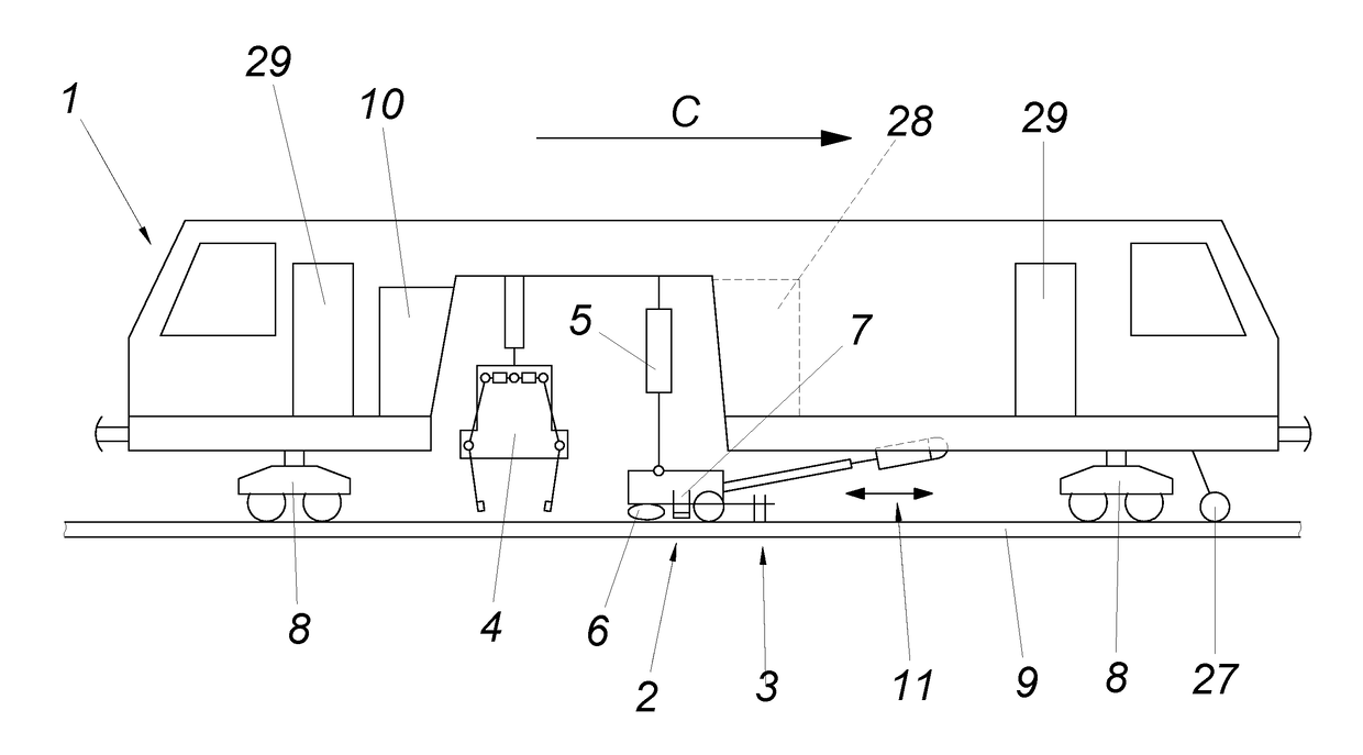
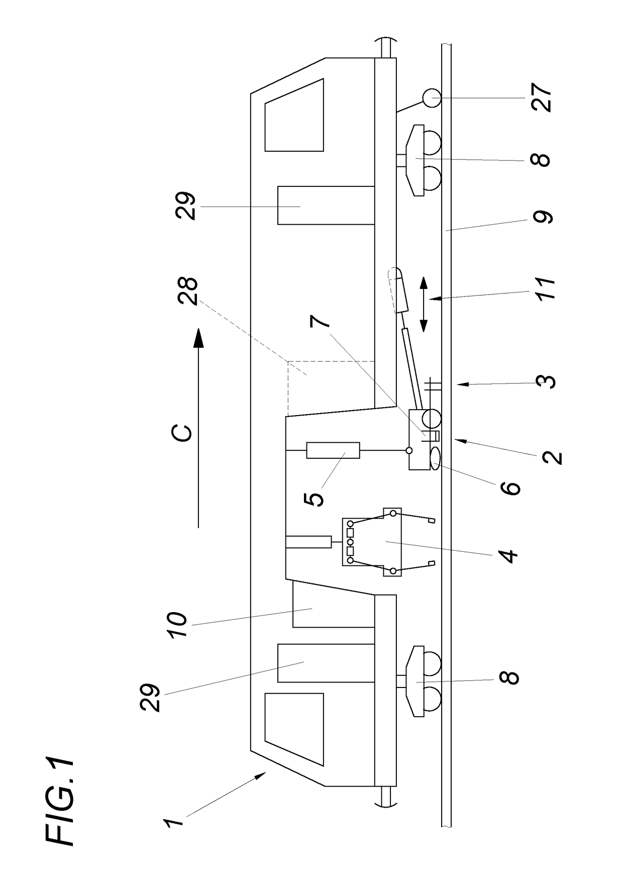
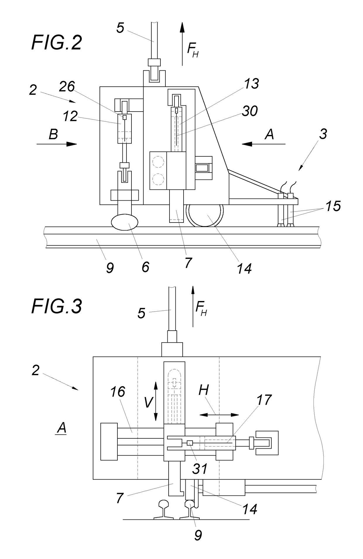
[0021]A switch tamping machine 1 comprises a tamping unit 4 and a track lifting and lining unit 2 comprising a lifting cylinder 5, a pair of roller pincers 6, a lifting hook 7 and a measuring device 3 (FIG. 1). The lifting and lining device can be displaced via a hydraulic cylinder in the longitudinal direction 11 of the track. The switch tamping machine is displaceable on the rail 9 via undercarriages 8. The control of the switch tamping machine 1 occurs from the working cabin 10 which is arranged in the working direction C behind the tamping unit 4. The working cabin 10 and the driver's cabs can be accessed via lateral doors 29. The arc length of the track is determined by a distance measuring device 27. The usually provided second switch tamping cabin 28 can be omitted in the embodiment in accordance with the invention. The switch component measuring system 3 for the position-dependent measurement of the position of switch components is provided upstream of the lifting and lining...


PUM


Abstract

A method and device for compacting the ballast bed of a track, especially in the region of a switch, comprising a switch tamping machine (1), which is fitted with a tamping unit (4), a lifting and lining device (2) comprising at least one pair of roller pincers (6) and at least one lifting hook (7) for lining the track position, and which is guided in a longitudinally displaceable manner on the machine frame (2) in the longitudinal direction of the machine. In order to provide advantageous lining conditions, it is proposed that a switch component measuring system (3), which is provided upstream of the lifting and lining device (2) in the working direction (C), is provided for the position-dependent measurement of the position of the switch components.

Description

FIELD OF THE INVENTION[0001]The invention relates to a method for controlling the lifting and lining device of a track-driveable switch tamping machine, comprising a tamping unit, one pair of roller pincers and at least one lifting hook, wherein the lifting and lining device is guided in a longitudinally displaceable manner in the longitudinal direction of the machine. Furthermore, a device is proposed for compacting the ballast bed of a track, especially in the region of a switch, with a switch tamping machine, which is fitted with a tamping unit with a lifting and lining device having at least one pair of roller pincers and at least one lifting hook for lining the track position.DESCRIPTION OF THE PRIOR ART[0002]Switch tamping machines are machines for correcting the track position of switches. Measurement systems are used for determining the track position which measure the actual height position of the track, the actual direction of the track and the actual position of the super...

Claims


Application Information

Patent Timeline
Patent Type & Authority Applications(United States)
IPC IPC(8): E01B27/17E01B35/06
CPCE01B27/17E01B35/06E01B2203/125E01B2203/10E01B27/20E01B35/00
Inventor LICHTBERGER, BERNHARD
Owner HP3 REAL GMBH
Learn More