Method and system for using a variable direction of view endoscope with a robotic endoscope holder

Active Publication Date: 2005-11-17
KARL STORZ IMAGING INC
View PDF12 Cites 44 Cited by
  • Summary
  • Abstract
  • Description
  • Claims
  • Application Information

AI Technical Summary

Problems solved by technology

The shortcoming of such endoscopic positioning systems is that they can only provide a limited endoscopic viewing range because the mechanical mobility is outside rat

Method used


Image

  • Method and system for using a variable direction of view endoscope with a robotic endoscope holder
  • Method and system for using a variable direction of view endoscope with a robotic endoscope holder
  • Method and system for using a variable direction of view endoscope with a robotic endoscope holder

Examples


embodiment

Preferred Embodiment

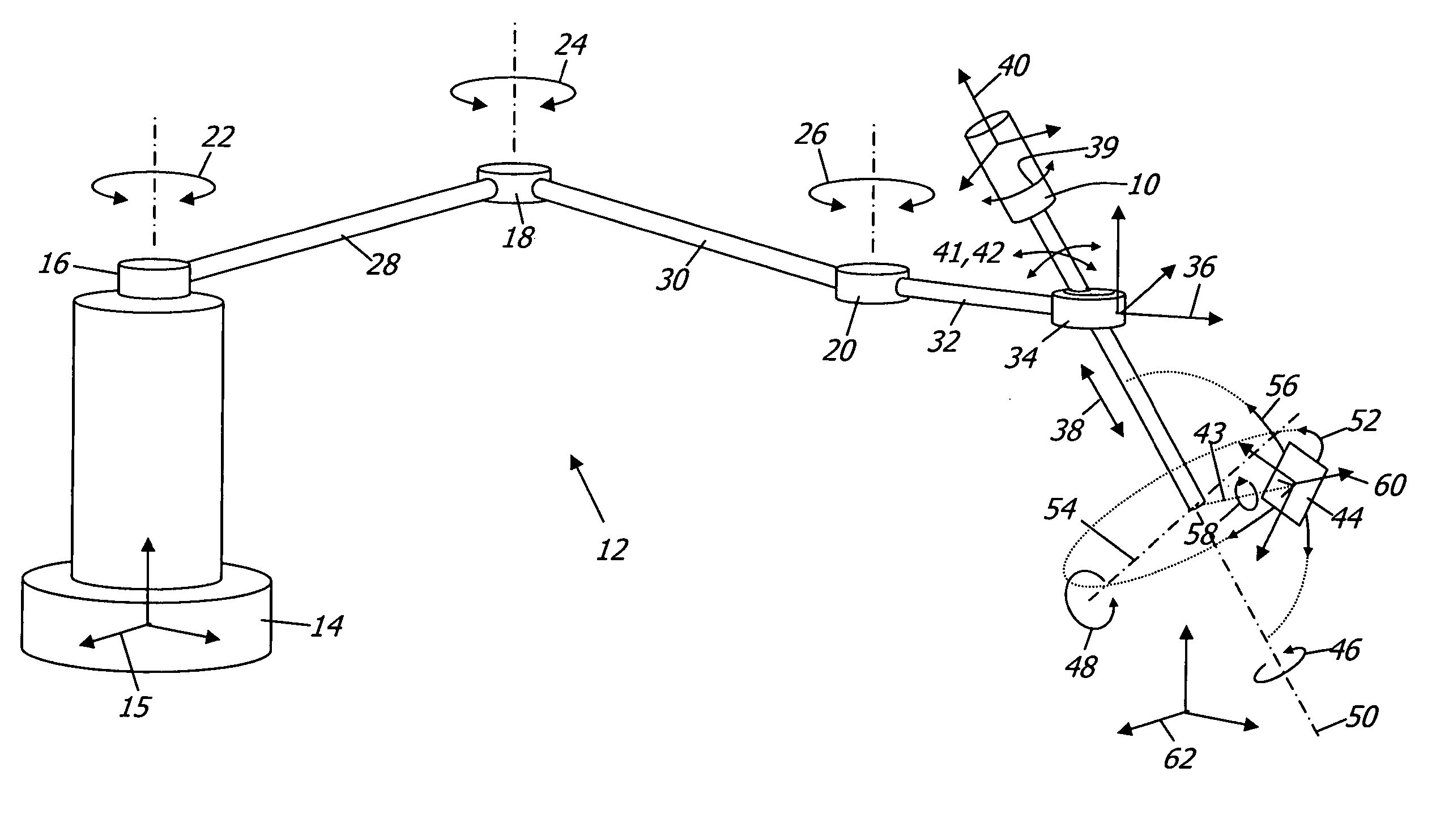
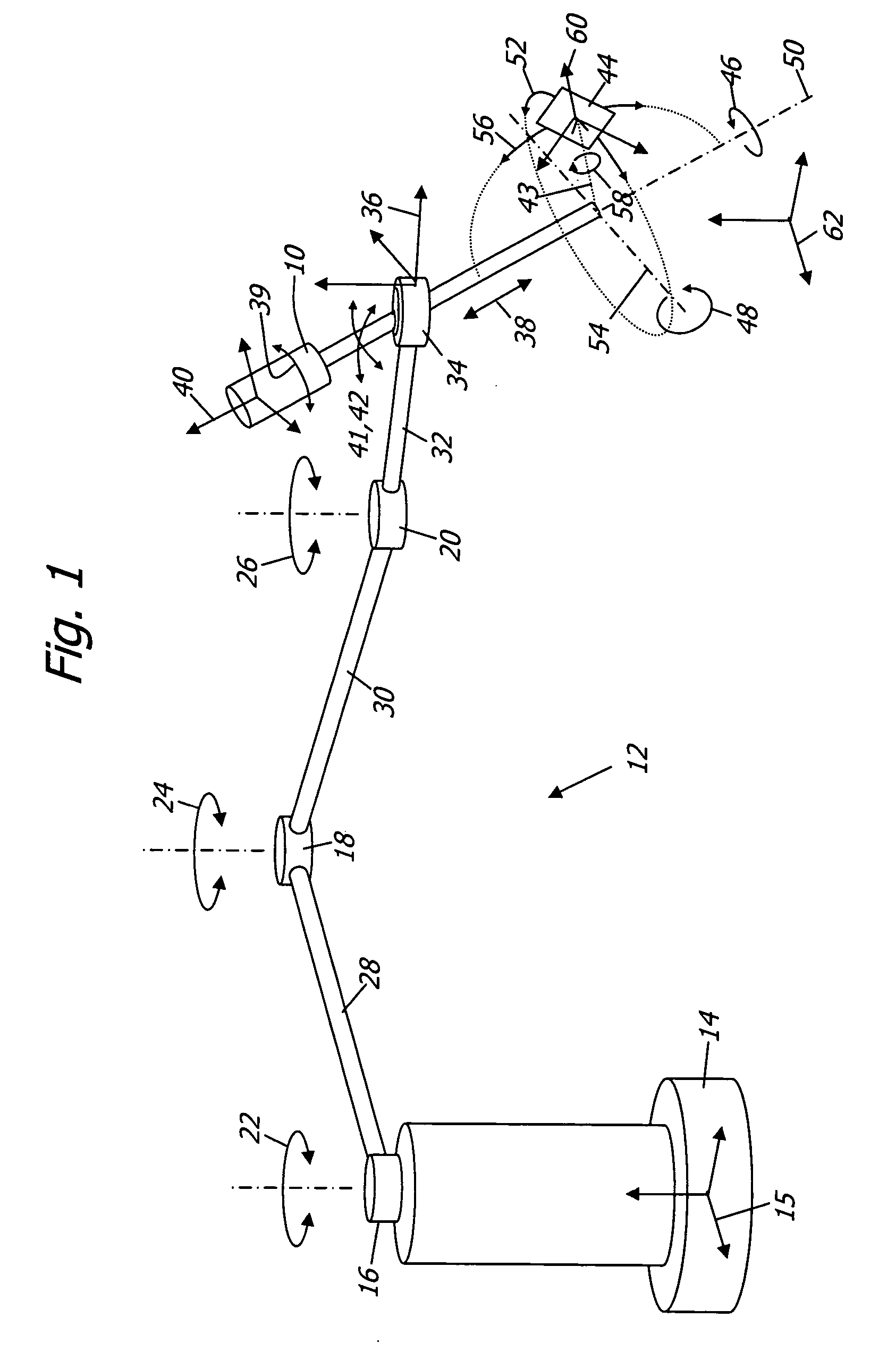
[0012] Referring now to the drawings, in which like reference numbers represent similar or identical structures throughout, FIG. 1 is a diagram of a basic variable direction of view endoscope 10 held by a robotic arm 12 with a base 14 and a base frame 15. The robotic arm 12 has three actuated revolute joints 16, 18, 20 with rotational degrees of freedom 22, 24, 26. The joints 16, 18, 20 are connected by links 28, 30. A third link 32 extends from the joint 20 to an end-effector 34 which has a prismatic joint (not explicitly shown) and an associated tool frame 36. The dynamic spatial relationship between the tool frame 36 and the base frame 15 is determined by the geometry of the joints 16, 18, 20 and links 28, 30, 32 and is in robotics called the forward kinematic transformation (or conversely the inverse kinematic transformation). Aside from the ability to slide and rotate the endoscope 10 along a linear degree of freedom 38 and a rotational degree of freedom 39,...


PUM


Abstract

A system and method for using a variable direction of view endoscope in conjunction with an electromechanical endoscope holder.

Description

CROSS-REFERENCE TO RELATED APPLICATIONS [0001] This application claims the benefit of U.S. provisional application Ser. No. 60 / 554,973 filed on Mar. 20, 2004, entitled “Method and system for using a variable direction of view endoscope with a robotic endoscope holder”, the contents of which are incorporated herein by reference.FIELD OF THE INVENTION [0002] The present invention relates to electromechanical positioning of variable direction of view endoscopes. BACKGROUND OF THE INVENTION [0003] Computer-controlled electromechanical positioning systems for endoscopes are disclosed in U.S. Pat. No. 5,515,478 to Wang and U.S. Pat. No. 5,524,180 to Wang et al. These multi degree-of-freedom devices provide the operator with the ability to accurately control the endoscopic viewing direction through electronic switches or voice commands and have become an important part of robotic minimally invasive surgical procedures. The shortcoming of such endoscopic positioning systems is that they can...

Claims


Application Information

Patent Timeline
IPC IPC(8): A61B1/00A61B1/313A61B19/00
CPCA61B1/00149A61B1/313A61B34/30A61B90/361A61B90/50
Inventor SCHARA, NATHANHALE, ERICHOEG, HANS
Owner KARL STORZ IMAGING INC
Why Eureka
Try Eureka