C-shaped heart valve prostheses

a heart valve and prosthesis technology, applied in the field of c-shaped heart valve prosthesis, can solve the problems of not being the best shape for providing the most effective and beneficial prosthesis

Inactive Publication Date: 2005-11-17
ST JUDE MEDICAL LLC
View PDF26 Cites 131 Cited by
  • Summary
  • Abstract
  • Description
  • Claims
  • Application Information

AI Technical Summary

Problems solved by technology

This may not be the best shape for providing the most effective and beneficial prosthesis.

Method used


Image

  • C-shaped heart valve prostheses
  • C-shaped heart valve prostheses
  • C-shaped heart valve prostheses

Examples


Embodiment Construction

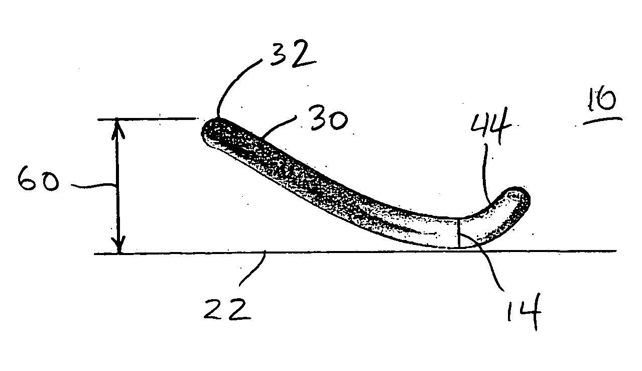
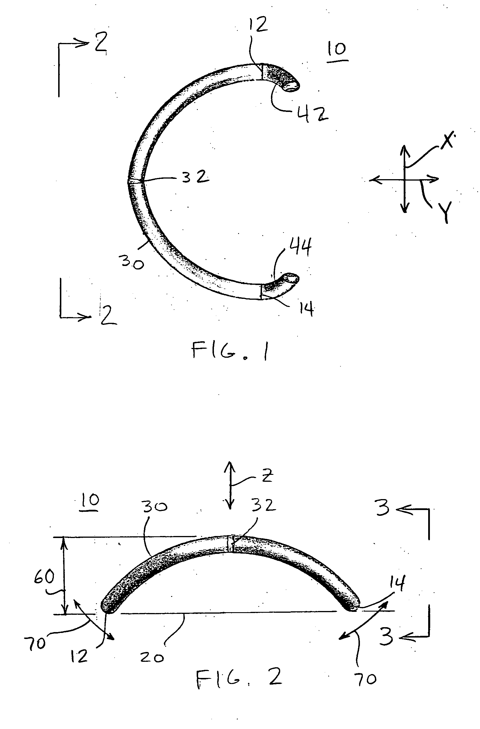
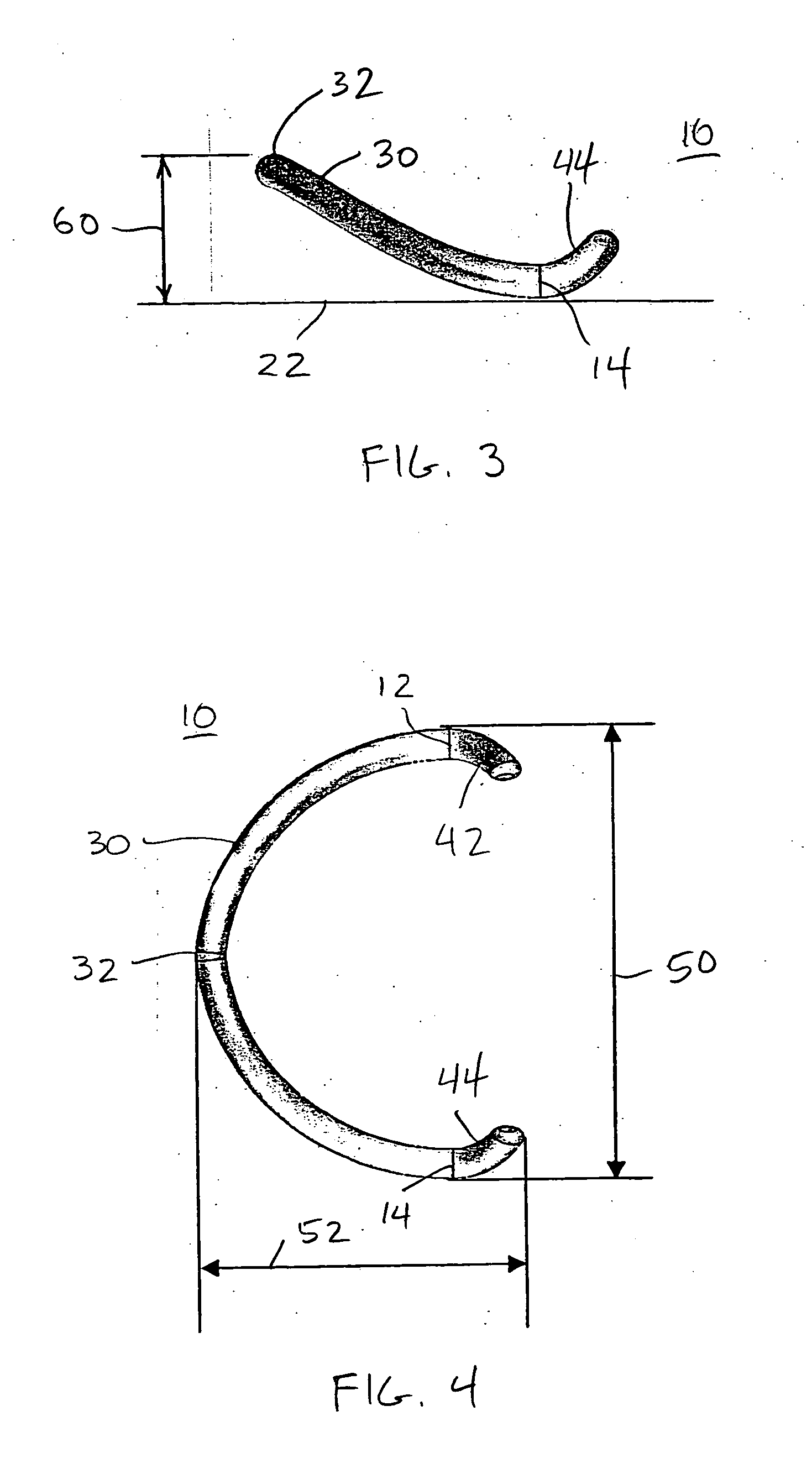
[0011] An illustrative embodiment of a heart valve prosthesis 10 in accordance with the invention is shown in FIGS. 1-4. This illustrative embodiment is intended for use as a mitral valve prosthesis. In that application prosthesis 10 will be implanted part way around a patient's mitral valve, with the posterior portion of the valve on the left as viewed in FIG. 1.

[0012] Prosthesis 10 is generally C shaped in plan view (see FIGS. 1 and 4). An upper medial point 12 and a lower medial point 14 of the C may be thought of as lying in a plan view plane of the prosthesis. This plan view plane is indicated by the (imaginary) line 20 in FIG. 2. Line 22 (also imaginary) in FIG. 3 also lies in this plane. Thus lines 20 and 22, which are perpendicular to one another, define the referenced plan view plane. Points 12 and 14 are referred to as medial, not because they are at the midpoint(s) of any structure, but only because they are interior to the length of the C-shaped structure (i.e., not at ...


PUM


Abstract

A prosthesis for a heart valve (e.g., the mitral valve) is generally C-shaped in plan view. Points at the top and bottom of the C lie in a plan view plane. The back of the C rises above the plan view plane between the top and bottom points. Free end portions of the C may also rise above the plan view plane. The prosthesis is accordingly saddle-shaped. The back of the C may have an indentation that extends toward the open side of the C. In use as a mitral valve prosthesis the top and bottom of the C are respectively adjacent the commissures of the valve, and the back of the C is adjacent the posterior section of the valve. The prosthesis may be rigid or semi-rigid.

Description

[0001] This application claims the benefit of U.S. provisional patent application No. 60 / 571,087, filed May 14, 2004, which is hereby incorporated by reference herein in its entirety.BACKGROUND OF THE INVENTION [0002] Annuloplasty rings are well known as prostheses for heart valves that are not functioning properly. See, for example, Alfieri et al. U.S. patent application publication U.S. 2002 / 0173844 A1 and Bolling et al. U.S. patent application publication U.S. 2003 / 0093148 A1. Prostheses that are less than complete rings are also known for this purpose. See, for example, Carpentier U.S. Pat. No. 3,656,185. The less-than-complete rings that are known tend to be flat. This may not be the best shape for providing the most effective and beneficial prosthesis. This invention aims at providing less-than-complete-ring prostheses having more effective shapes and other beneficial features. SUMMARY OF THE INVENTION [0003] A heart valve prosthesis in accordance with the invention is general...

Claims


Application Information

Patent Timeline
Patent Type & Authority Applications(United States)
IPC IPC(8): A61F2/24
CPCA61F2/2448
Inventor LIM, JYUE BOONSUTTON, WILLIAM M.
Owner ST JUDE MEDICAL LLC
Why Eureka
Try Eureka