Heat fusing apparatus, method of controlling same and image forming apparatus

a heat fusion and image forming technology, applied in the direction of temperatue control, process and machine control, instruments, etc., can solve the problems of abnormality sensing devices, peripheral devices to be subjected to damage such as deformation and degradation, and the damage of apparatuses, so as to minimize the cost of replacement parts and service cost , the effect of minimizing the damage of apparatus

Active Publication Date: 2005-11-24
CANON KK
View PDF21 Cites 31 Cited by
  • Summary
  • Abstract
  • Description
  • Claims
  • Application Information

AI Technical Summary

Benefits of technology

[0009] Accordingly, an object of the present invention is to provide a heat fusing apparatus, a method of controlling same and an image forming apparatus having this heat fusing apparatus for preventing, without malfunction at the time of normal operation, the occurrence of a situation in which the entire fusing apparatus and peripheral devices must be repaired or replaced owing to the above-mentioned overheating, and for minimizing apparatus damage to thereby minimize the cost of replacement parts and service cost.

Problems solved by technology

Furthermore, there is the danger that the apparatus will be destroyed by overheating when energization runaway occurs.
Further, there are abnormality sensing devices in which the output of a thermister is compared with a reference voltage and the heater forcibly opened.
In actuality, however, owing to an excessive rise in environmental temperature from onset of overheating trouble in the fusing apparatus to actuation of the safety device such as a thermostat, not only such members as a pressure roller and ceramic heaters inside the fusing apparatus but also devices peripheral thereto are subjected to damage such as deformation and degradation.
If the operating temperature is set very low, however, the abnormal-overheat safety device will be actuated at the time of normal operation and the image forming apparatus will malfunction.

Method used


Image

  • Heat fusing apparatus, method of controlling same and image forming apparatus
  • Heat fusing apparatus, method of controlling same and image forming apparatus
  • Heat fusing apparatus, method of controlling same and image forming apparatus

Examples


first embodiment

[0034] An embodiment of the present invention will now be described based upon the drawings.

(1) Example of Structure of Image Forming Apparatus

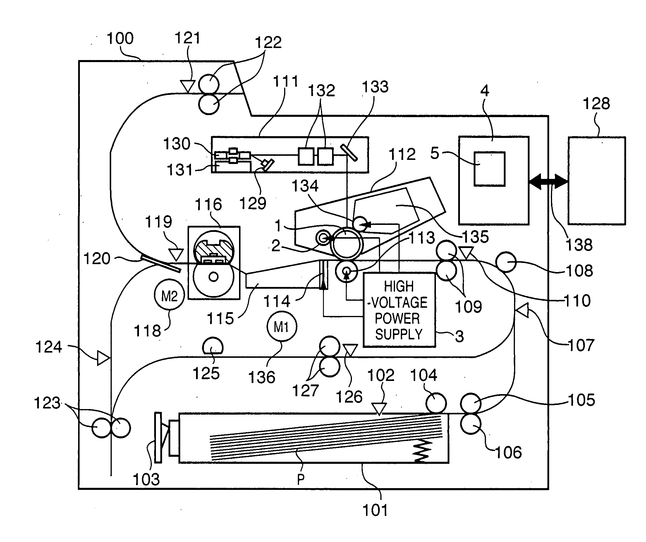
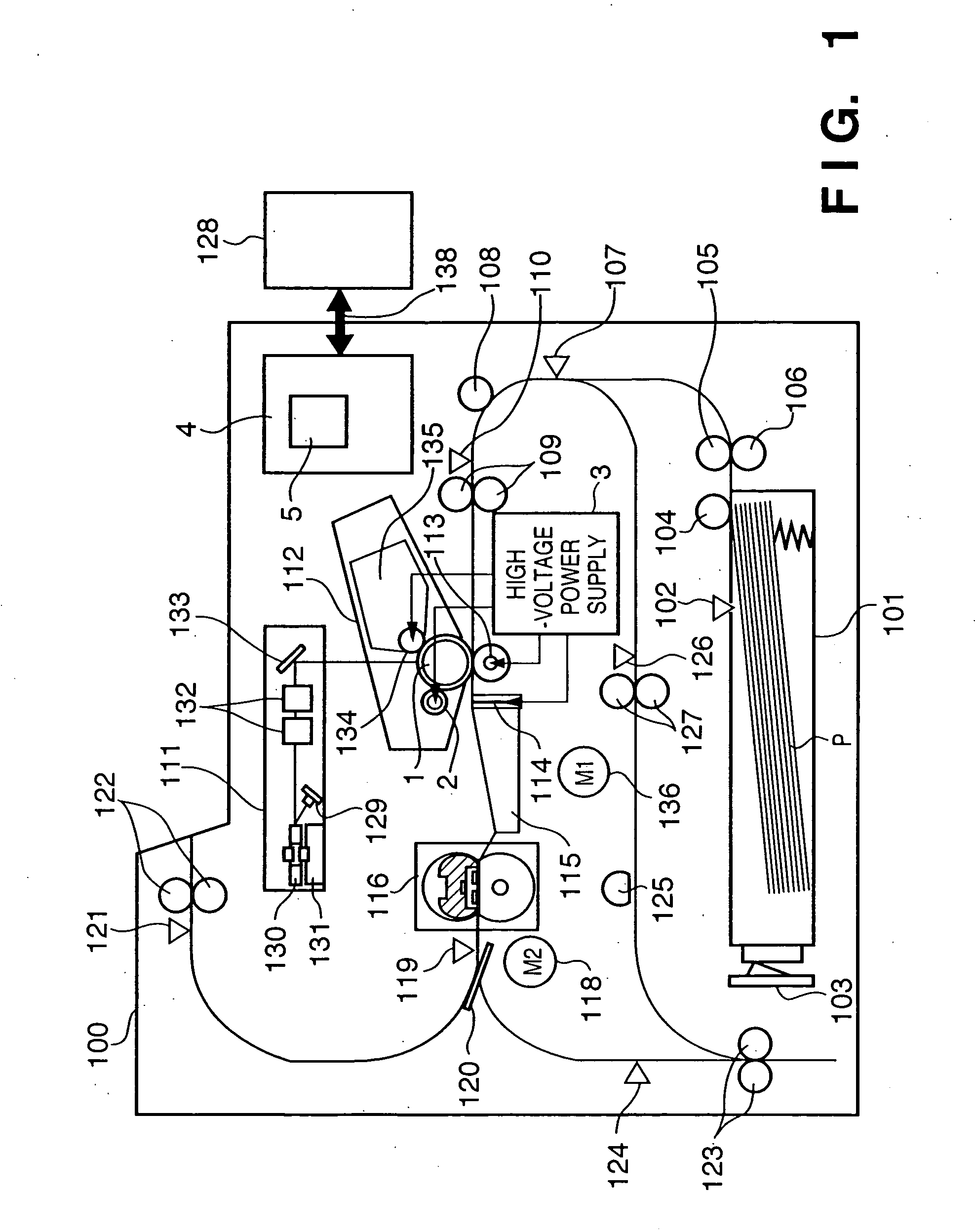
[0035]FIG. 1 is a diagram illustrating the structure of a laser printer 100 according to this embodiment.

[0036] The laser printer 100 has a deck 101 that stores printing paper P and is provided with a deck paper sensor for sensing whether the deck 101 contains the printing paper P, a paper size sensor 103 for sensing the size of the printing paper P in the deck 101, a pick-up roller 104 for feeding the printing paper P from the deck 101, a deck paper feeding roller 105 for transporting the printing paper P fed by the pick-up roller 104, and a retard roller 106, which forms a pair with the deck paper feeding roller 105, for preventing overlapping feed of the printing paper P.

[0037] Disposed downstream of the deck paper feeding roller 105 are the deck 101, a paper feed sensor 107 for sensing the state of paper feed and transport from a dou...

second embodiment

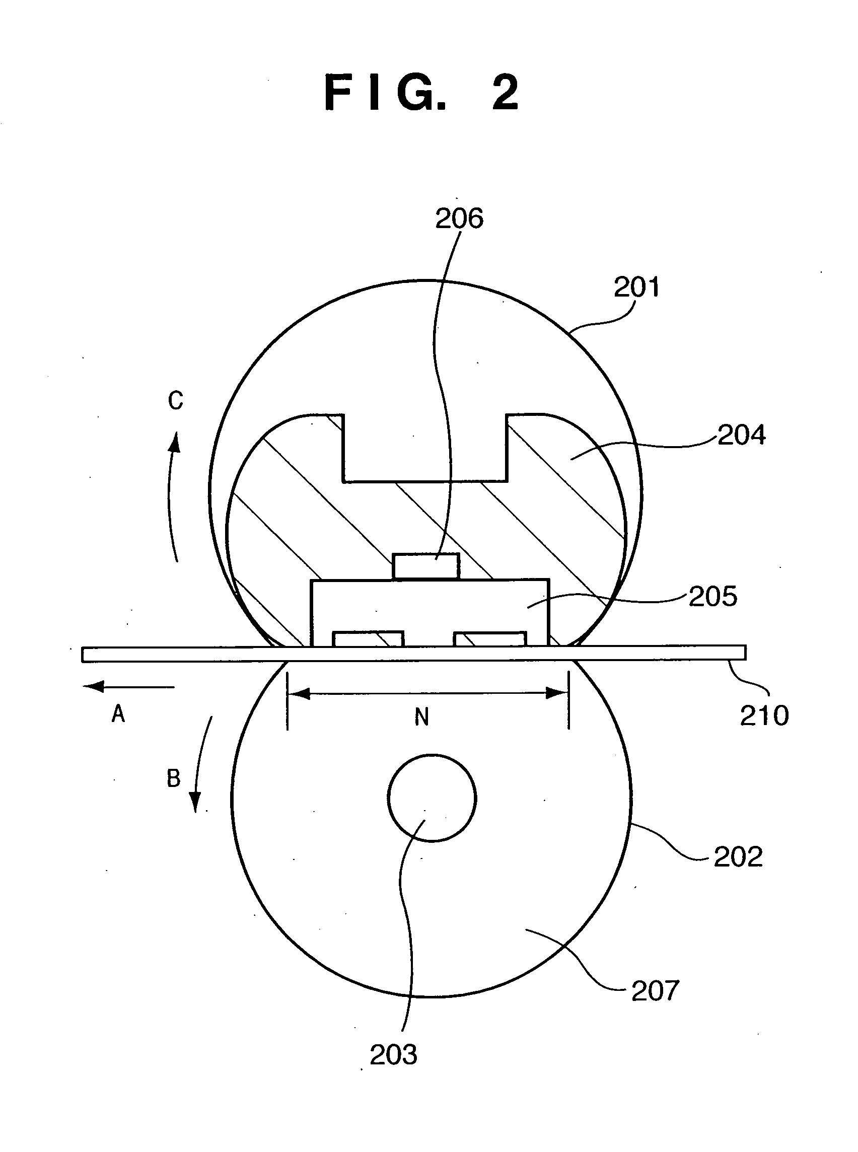
[0084] A second embodiment of the present invention will now be described. In the first embodiment, the level of the criterion of abnormal overheating of a plurality of thermisters is changed over in accordance with the result of detecting the current of a ceramic heater. The basic structure of the second embodiment is the same as that of the first embodiment but is characterized in that criterion for judging abnormal overheating is changed over in accordance with the state of rotation of a pressure roller. Only the elements of the second embodiment that differ from those of the first embodiment will be described.

(1) Example of Sensing of Rotation of Fusing Drive Motor

[0085]FIG. 11 is a diagram showing the circuit structure according to this embodiment.

[0086] Reference numeral 118 denotes the fusing drive motor M2 for rotating the pressure roller 202. The fusing drive motor M2 (118) is controlled to rotate at a constant speed by an ACC signal, BLK signal and FG (Frequency Genera...


PUM


Abstract

Disclosed is a heat fusing apparatus for thermally fusing toner that has been transferred to a printing medium from a toner image formed on an image bearing member using an electrophotographic process. Temperature is detected at the surface of a heating element or in the vicinity thereof. If control is performed so as to interrupt supply of power to the heating element based upon result of comparing the detected temperature and a reference value, the amount of current that flows into the heating element is detected and the reference value is changed over in accordance with the result of detection. Further, a pressure roller, which is a rotation member placed opposite the heating element, presses the printing medium against the heating element and transports the printing medium. The state of rotation of the roller is detected and the reference value is changed over in accordance with the result of detection. The apparatus prevents, without malfunction at the time of normal operation, the occurrence of a situation in which the entire fusing apparatus and peripheral devices must be repaired or replaced owing to overheating, and minimizes apparatus damage to thereby minimize the cost of replacement parts and service cost.

Description

FIELD OF THE INVENTION [0001] This invention relates to an image forming apparatus such as a copier, printer or facsimile machine that employ an electrophotographic process, and to a multifunction apparatus that is a combination of these devices. More particularly, the invention relates to a heat fusing apparatus in an image forming apparatus and to a method of controlling the same. BACKGROUND OF THE INVENTION [0002] A known thermal-type fusing apparatus used in an image forming apparatus has an energized heating element serving as a heat source, a power supply for supplying current to the heating element, temperature detecting means for detecting temperature in the vicinity of the heating element, and control means for controlling the supply of current from the power supply based upon a signal from the temperature detecting means. A printing medium carrying an unfixed image formed thereon by an image forming section of the image forming apparatus is heated and fused onto the medium...

Claims


Application Information

Patent Timeline
Patent Type & Authority Applications(United States)
IPC IPC(8): G05D23/24G03G15/20H05B1/00
CPCG05D23/2434G03G2215/2035G03G15/2042G05D23/24G05D23/1932
Inventor TAKAMI, HIROSHIMAKIHIRA, TOMOYUKI
Owner CANON KK
Why Eureka
Try Eureka