Pipe coupling having compression band

a compression band and pipe coupling technology, applied in the field of couplings, can solve the problems of manual manipulation of the seal, tedious and time-consuming installation process of mechanical couplings,

Active Publication Date: 2005-11-24
VICTAULIC
View PDF42 Cites 84 Cited by
  • Summary
  • Abstract
  • Description
  • Claims
  • Application Information

AI Technical Summary

Benefits of technology

[0008] Preferably, the segments are spaced apart from one another at substantially equal intervals. In order to maintain the spacing of the segments, one or more projections are mounted on either the band or the segments. The projections limit relative motion between the band and the segments and serve to hold the segments at a predetermined position relatively to the band. Preferably, the projections are attached to the segments and extend substantially radially outwardly. The band has apertures therethrough or indentations at spaced intervals for receiving the projections.

Problems solved by technology

This geometrical relation between the arcuate surfaces of the couplings and the outer surfaces of the pipe elements in prior art couplings results in a tedious and time consuming installation process when mechanical couplings are used.
Installation of the ring seal requires that it be lubricated and stretched to accommodate the pipe elements, an often difficult and messy task, as the ring seal is usually stiff and the lubrication makes manual manipulation of the seal difficult.

Method used


Image

  • Pipe coupling having compression band
  • Pipe coupling having compression band
  • Pipe coupling having compression band

Examples


embodiment 11

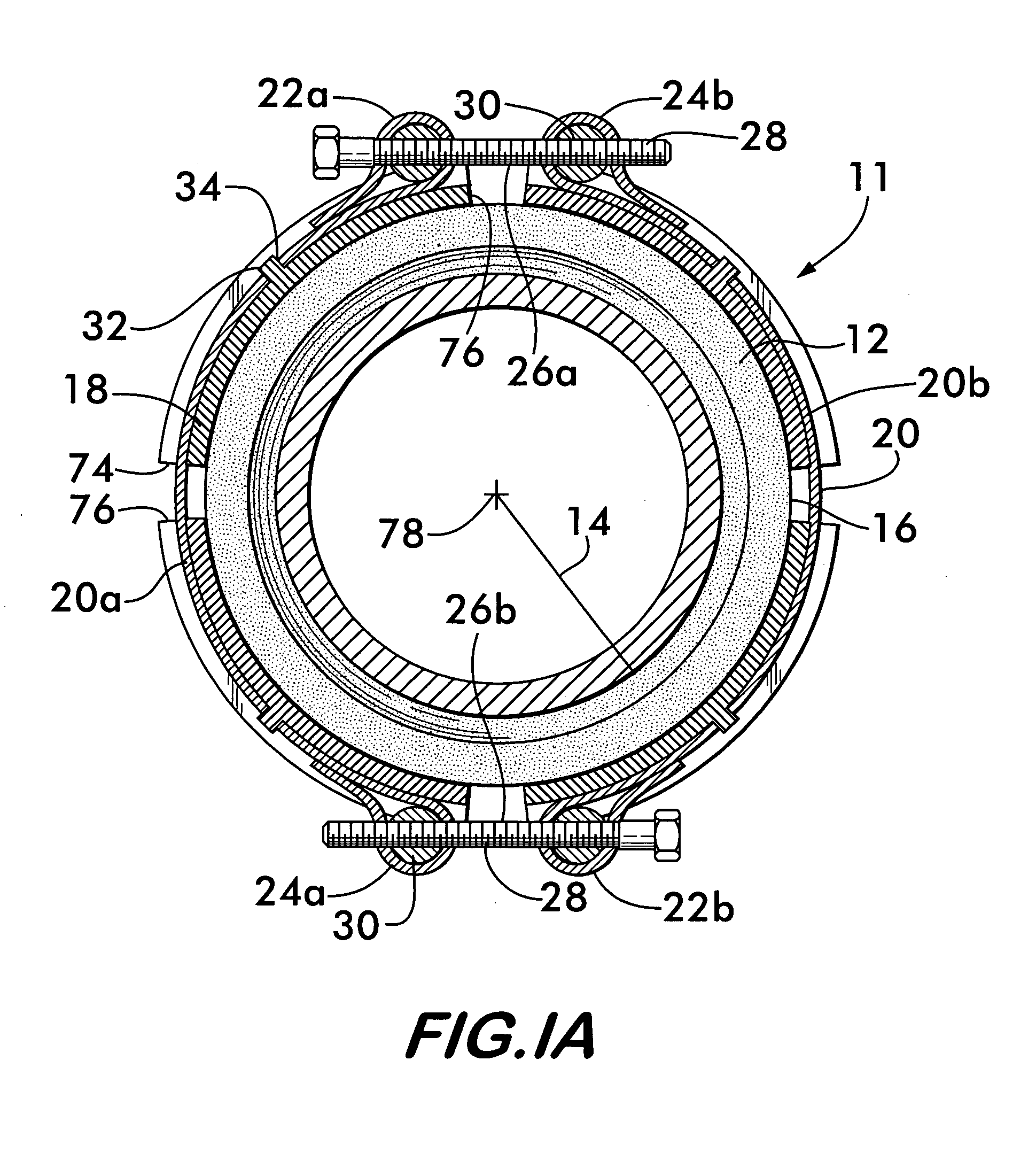
[0025]FIG. 1A illustrates an alternate coupling embodiment 11 wherein compression band 20 is divided into a plurality of band portions, in this example, two portions, 20a and 20b. Each band portion has opposite ends 22a and 24a, and 22b and 24b respectively, which are positioned adjacent to one another so as to arrange the band portions in end to end relationship around the segments 18. The ends in facing relation, 22a and 24b, and 22b and 24a, are joined by respective tensioning members 26a (mounted between 22a and 24b) and 26b (mounted between 22b and 24a). Each tensioning member preferably also comprises a bolt 28, mounted on one end of a band portion (22a and 22b), the bolt engaging a threaded body 30 mounted on the adjacent end portion (24a, 24b). Tightening of the tensioning members applies tension to the band portions and forces the segments 18 radially inwardly against the sealing member 12. Compression band couplings having two or more band portions and the appropriate numb...

embodiment 80

[0032] While projecting arcuate surfaces engageable with grooved pipes are a preferred embodiment, the coupling according to the invention may also be used to join plain end pipe elements. Such an embodiment 80 is shown in FIG. 2B, wherein segments 18 have arcuate surfaces 40 and 42 that may comprise a tooth or teeth 82 and 84. The teeth, when present, face substantially radially inwardly to grip the outer surface of plain pipe elements and provide mechanical restraint to the joint when the tensioning member of the coupling is tightened and the segments are forced into engagement with the pipe elements. The teeth may extend substantially continuously around the segment as illustrated by teeth 82, or they may be a single tooth 84, or a plurality of single teeth 84 spaced apart at intervals from one another.

embodiment 79

[0033] In an alternate coupling embodiment 79, shown in FIGS. 3 and 3A, segments 18 have opposite end faces 86 and 88 that are angularly oriented with respect to the longitudinal axis 78 of the pipe elements. This angular orientation is best shown in FIGS. 7 and 7A. FIG. 7 shows an axial view of a single segment 18 from coupling 79 wherein end faces 86 and 88 are visible. FIG. 7A shows the segment 18 of FIG. 7 as it would appear looking inwardly toward axis 78 to render the relative orientation of both end faces 86 and 88 visible and thus emphasize the angular relation between the end faces and the axis 78. Note that the end faces on each segment have opposite slopes. Furthermore, as shown in FIGS. 3 and 3A, the end faces 86 and 88 on neighboring segments 18 are substantially parallel to one another. In this embodiment, the segments are sized so that the end faces 86 on each segment engage the end faces 88 on each neighboring segment upon tightening of the tensioning member and as t...


PUM

PropertyMeasurementUnit
inner diameteraaaaaaaaaa
tensionaaaaaaaaaa
flexibleaaaaaaaaaa

Abstract

A coupling for joining pipe elements in end to end relationship is disclosed. The coupling includes a sealing member having an inner diameter and an outer surface. A plurality of segments are supported on the sealing member's outer surface. Each segment has a pair of arcuate surfaces positioned in space relation on either side of the sealing member. A compression band surrounds the outer perimeter of the segments, the segments being captured between the band and the sealing member. The pipe elements are inserted into the inner diameter between the segments. A tensioning member is mounted on the band. Tightening of the tensioning member causes the compression band to force the segments radially inwardly into engagement with outer surfaces of the pipe elements.

Description

FIELD OF THE INVENTION [0001] This invention concerns couplings for joining pipe elements end to end, the couplings having multiple segments held together by a compression band. BACKGROUND OF THE INVENTION [0002] Mechanical couplings for joining pipe elements together end-to-end comprise interconnectable segments that are positionable circumferentially surrounding the end portions of co-axially aligned pipe elements. The term “pipe element” is used herein to describe any pipe-like item or component having a pipe like form. Pipe elements include pipe stock, pipe fittings such as elbows, caps and tees as well as fluid control components such as valves, reducers, strainers, restrictors, pressure regulators and the like. [0003] Each mechanical coupling segment comprises a housing having arcuate surfaces which project radially inwardly from the housing and engage plain end pipe elements or circumferential grooves that extend around each of the pipe elements to be joined. Engagement betwe...

Claims


Application Information

Patent Timeline
Patent Type & Authority Applications(United States)
IPC IPC(8): F16L3/00F16L17/00F16L17/025F16L21/02F16L21/06F16L23/032F16L23/04F16L23/08F16L23/18F16L25/14F16L33/04
CPCF16L17/04F16L21/065F16L23/08F16L21/005F16L25/14F16L21/02Y10T29/53987F16L23/18F16L17/00
Inventor GIBB, JOHN
Owner VICTAULIC
Why Eureka
Try Eureka