Mechanism for selectively operating hopper doors of a railroad car

a technology for operating mechanisms and railroad cars, which is applied in the direction of railway components, tipping wagons, wagons/vans, etc., can solve the problems of limiting the open area of the car's bottom, additional costs and potential damage to the car, and the operation mechanism of the hopper door

a technology for operating mechanisms and railroad cars, which is applied in the direction of railway components, tipping wagons, wagons/vans, etc., can solve the problems of limiting the open area of the car's bottom, additional costs and potential damage to the car, and the operation mechanism of the hopper door

US20050263032A1Inactive Publication Date: 2005-12-01VERTEX RAILCAR CORP

Image

  • Mechanism for selectively operating hopper doors of a railroad car
  • Mechanism for selectively operating hopper doors of a railroad car
  • Mechanism for selectively operating hopper doors of a railroad car

Examples


Embodiment Construction

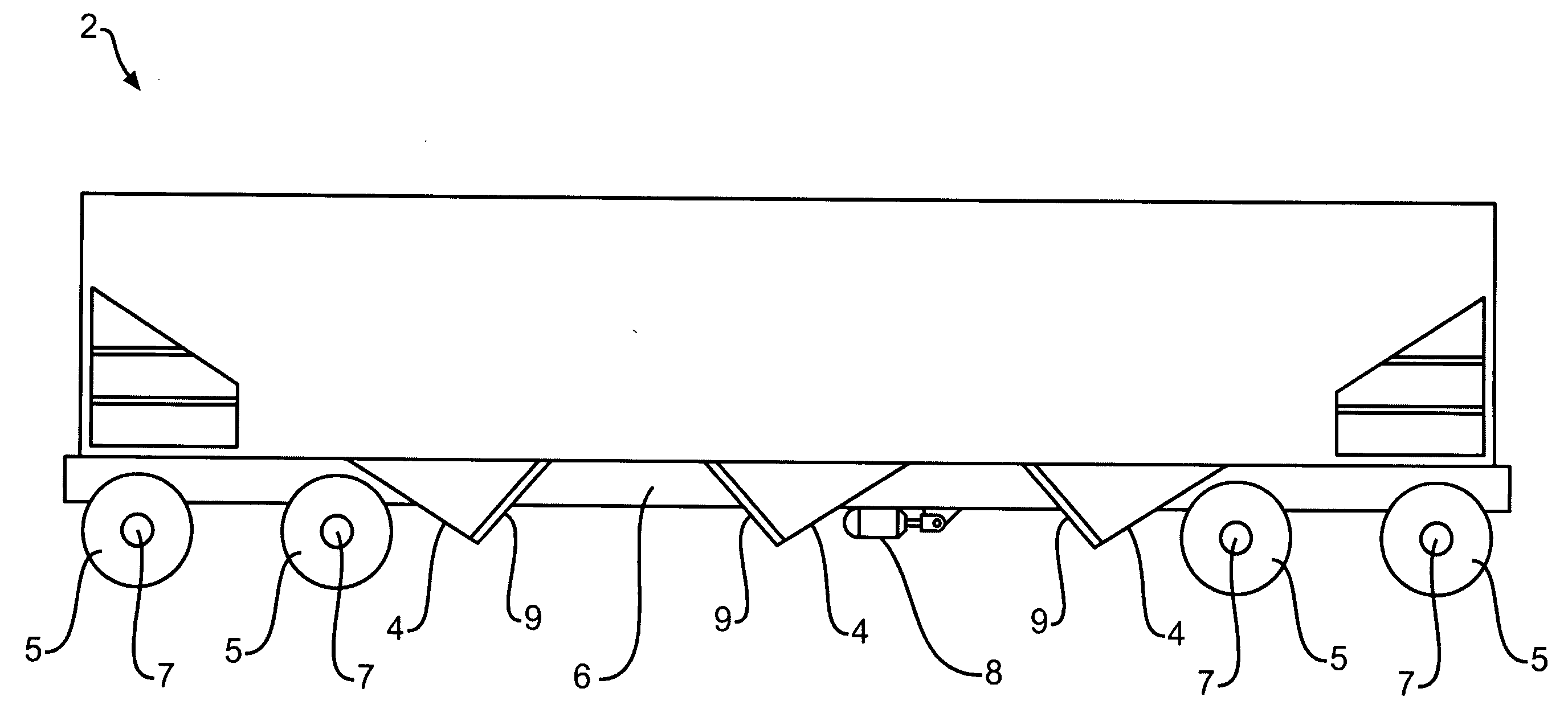
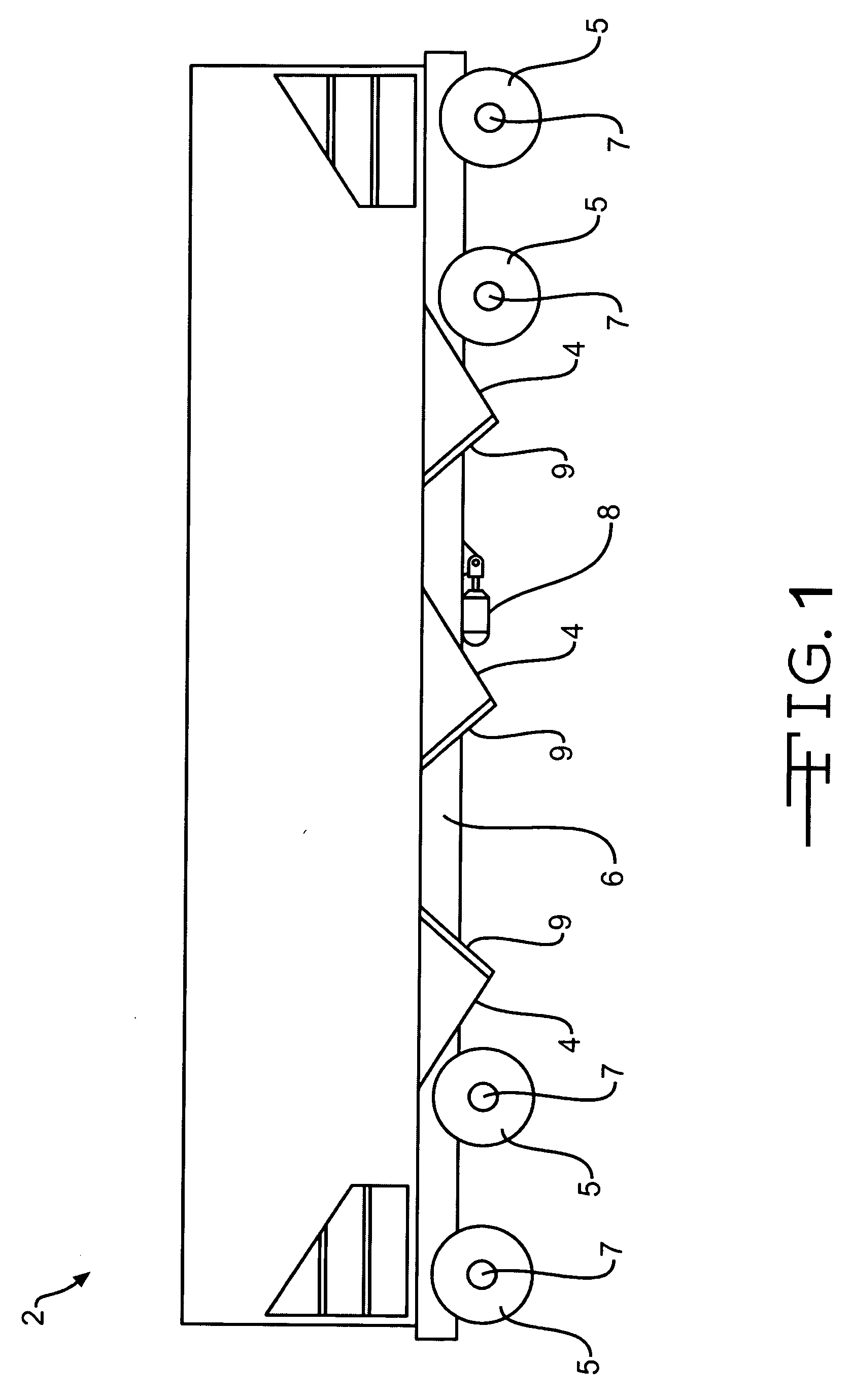
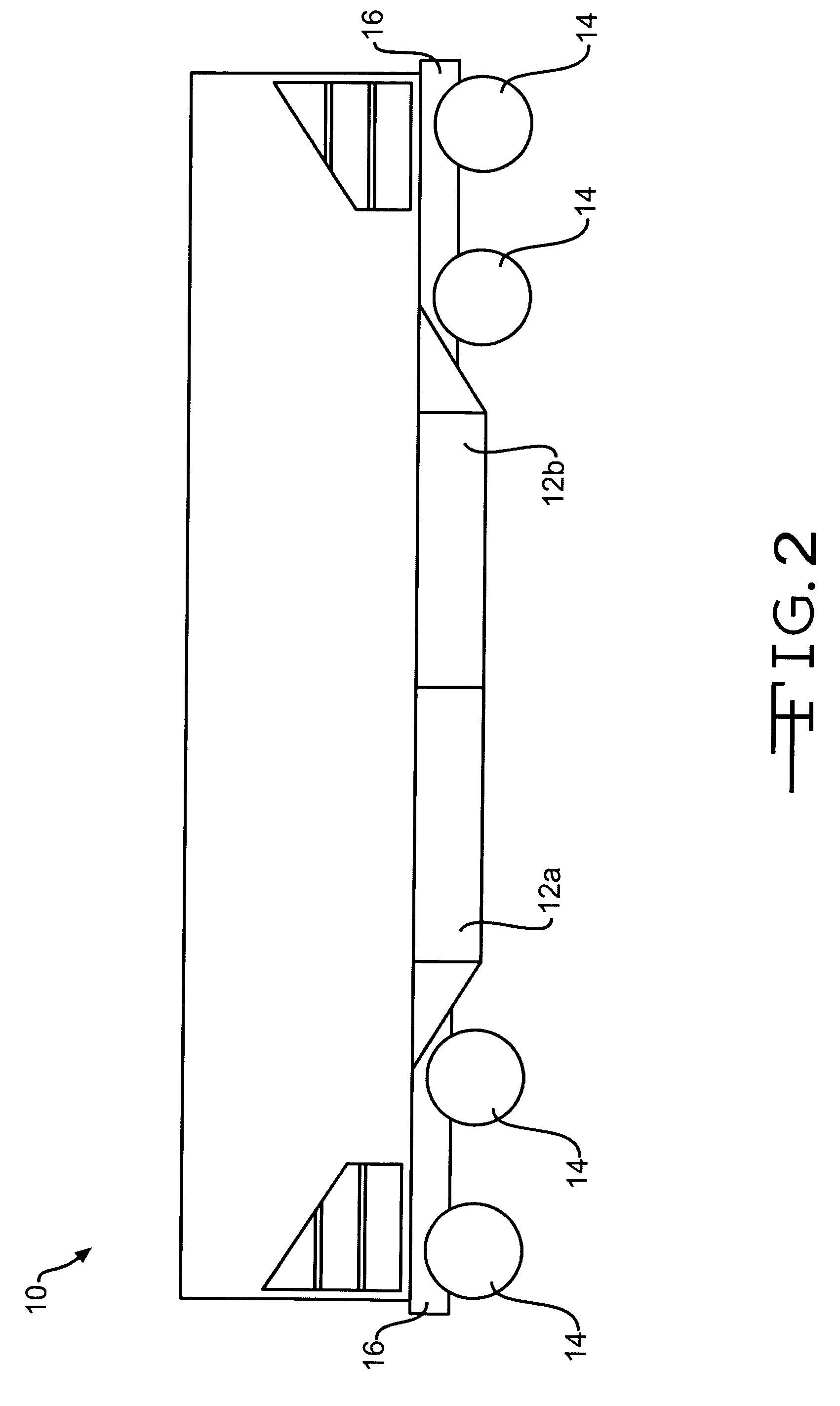
[0034]FIGS. 1-3 display three different major types of hopper cars. FIGS. 1 and 2 show hopper cars using transverse doors, while FIG. 3 shows a car using longitudinal doors.

[0035] Referring now to FIG. 1, there is shown a typical three pocket railway hopper car, generally designated at 2, which may be equipped with a preferred embodiment of the present invention. Car 2 is provided with a plurality of hopper units 4, a plurality of wheels 5, and a longitudinally extending center sill 6. Wheels 5 are mounted on a series of truck axles 7. An air cylinder 8 is mounted to car 2 on the underside of sill 6 to provide power for the actuating mechanism for the doors. The operation of air cylinder 8 is well known in the art, and it is within the scope of the present invention to use any suitable power source (electric, liquid, steam) to operate cylinder 8. Each hopper unit 4 is provided with a door 9 which is moveable to open and close each hopper unit 4. An actuating system for this type of...


PUM


Abstract

A mechanism for selectively operating hopper doors of a railroad car. A fulcrum coupled to the operating cylinder includes channels within which levers can be selectively activated to open specific doors of the car, thus allowing the contents of the railcar to be sequentially emptied. The mechanism can be installed on railcars having either transverse hopper doors or longitudinal hopper doors.

Description

CROSS REFERENCE TO RELATED APPLICATIONS [0001] This application claims benefit from U.S. Provisional Patent Application Ser. No. 60 / 574,761, filed May 27, 2004, which application is incorporated herein by reference.BACKGROUND OF THE INVENTION [0002] 1. Field of the Invention [0003] The present invention is directed in general to systems for operating railroad car hopper doors, and, in particular, to a system which selectively opens the doors on railroad hopper car doors. [0004] 2. Description of the Related Art [0005] A common type of railroad freight car in use today is the freight car of the type wherein the load is discharged through hoppers in the underside of the body. Such cars are generally referred to as hopper cars and are used to haul coal, phosphate and other commodities. [0006] After hopper cars are spotted over an unloading pit, the doors of the hoppers are opened, allowing the material within the hopper to be emptied into the pit. [0007] Hopper cars, which may be cover...

Claims


Application Information

Patent Timeline
01 Dec 2005
Publication
US20050263032A1
IPC
B61D3/00; B61D7/28
CPC
B61D7/28
Inventors
TAYLOR, FRED J.