Tire pressure regulating system

a technology of regulating system and tire, which is applied in the direction of electric propulsion mounting, machines/engines, tractors, etc., to achieve the effect of damping the sound, quick filling or emptying of tires, and no throttling losses

Inactive Publication Date: 2009-07-07
DEERE & CO
View PDF22 Cites 7 Cited by
  • Summary
  • Abstract
  • Description
  • Claims
  • Application Information

AI Technical Summary

Benefits of technology

[0035]For achieving a sufficiently quick filling or emptying of the tire, a hose coupling and / or a connecting line of the tire-pressure regulating system has at least a cross section or an open diameter of ½ in, i.e., approximately 1.3 cm. At such a cross section for the line, there are almost no throttling losses or temperature increases of the line parts.
[0036]In an extremely preferred embodiment of the tire-pressure regulating system according to the invention, means are provided with which the air pressure of the air moved into a tire can have an upper limit. Such means could have, for example, an automatic pressure switch which breaks the connection between the turbocharger and the tire when the air pressure exceeds a preset value. An upper air pressure limit could be, for example, 1.6 bar. This prevents, in the extreme case, the tire from bursting.
[0037]Furthermore, means could be provided with which the air pressure of the air moved out of the tire can have a lower limit. These means could also have, for example, an automatic pressure switch which breaks the connection between the tire and the surroundings when the air pressure falls below a preset value. This prevents the tire from completely deflating when letting air out of the tire and prevents the vehicle from being lowered onto the rims. A lower air pressure limit could be, for example, a value of 0.3 bar.
[0038]In detail, a non return valve could be provided between the turbocharger and a tire. This non return valve prevents excess pressure from the tire from acting on the turbocharger or from tire filling to occur only when the turbocharger side air pressure has a higher value than the wheel side air pressure.
[0039]In a preferred embodiment, there are means for damping the sound produced when air is let out of the tire. A large amount of noise is generated, in particular, for quick emptying of a tire, when a large air volume escapes through a hose coupling or through a connecting line into the surroundings. Preferably, the means for damping the sound has a pressure limiting valve.

Problems solved by technology

In principle, the problems for setting the dimensions of a turbocharger for an internal combustion engine consists in that the turbocharger must provide the necessary air compression for all of the operating conditions of the internal combustion engine.

Method used


Image

  • Tire pressure regulating system
  • Tire pressure regulating system
  • Tire pressure regulating system

Examples


Embodiment Construction

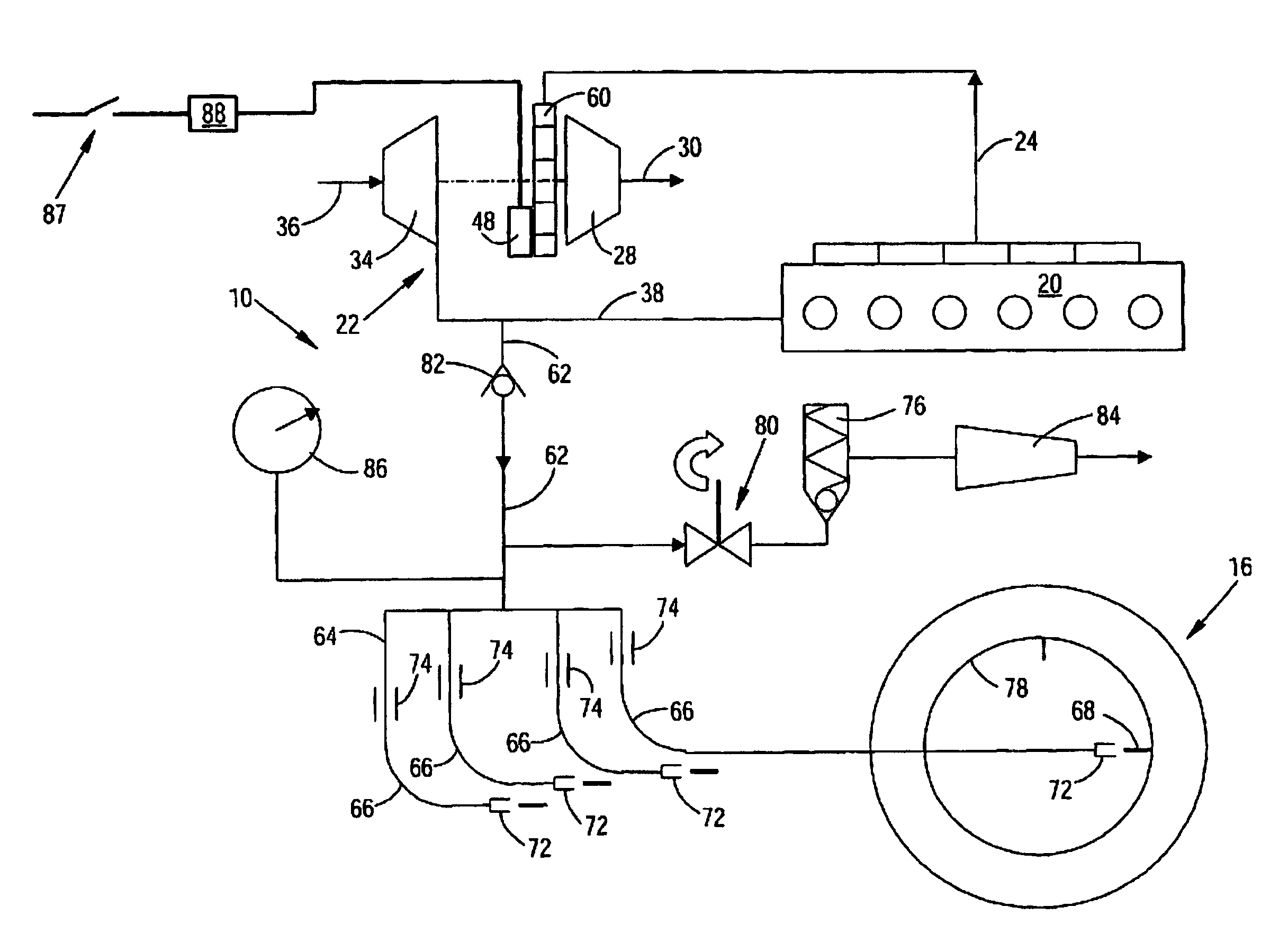
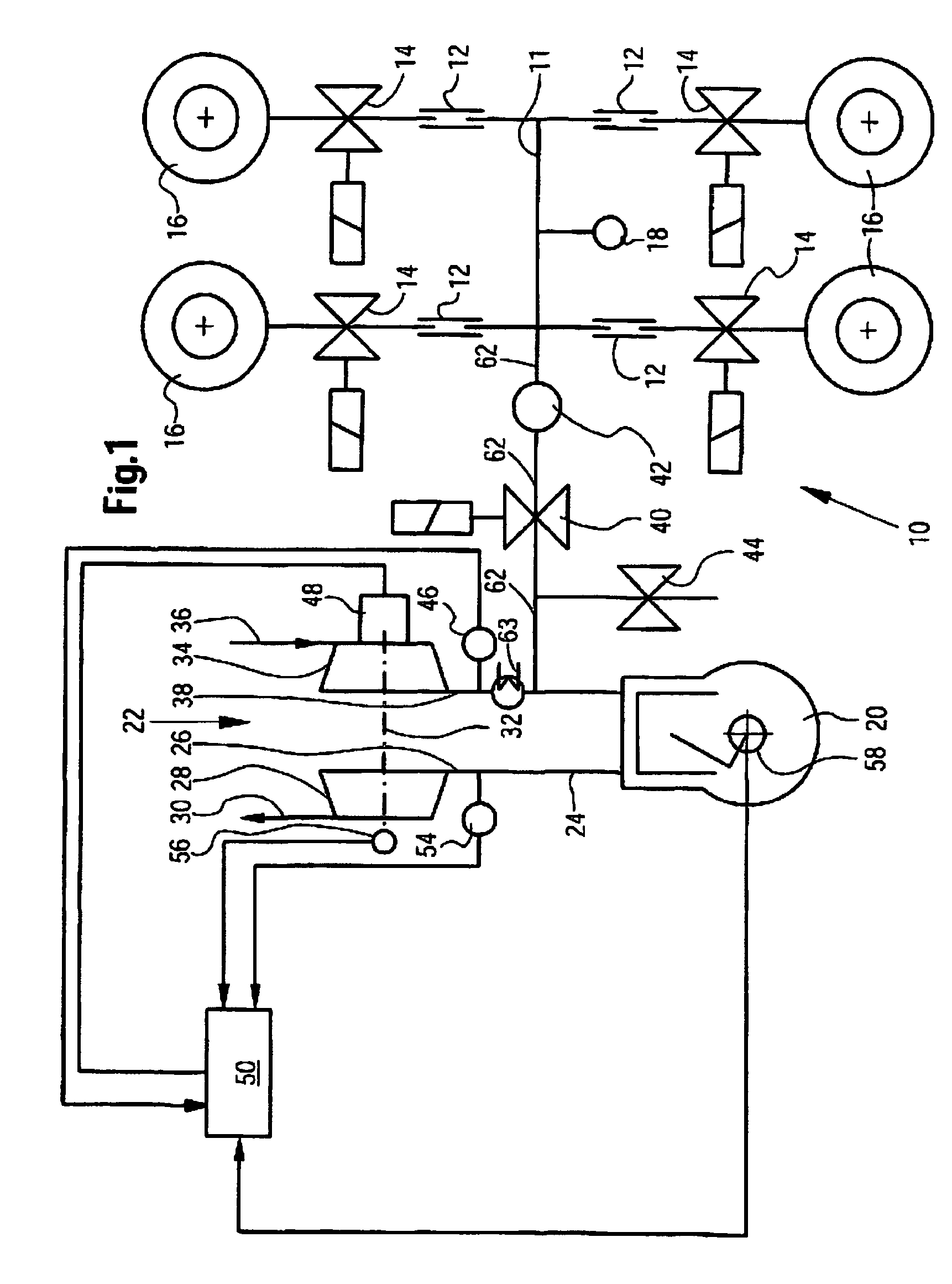
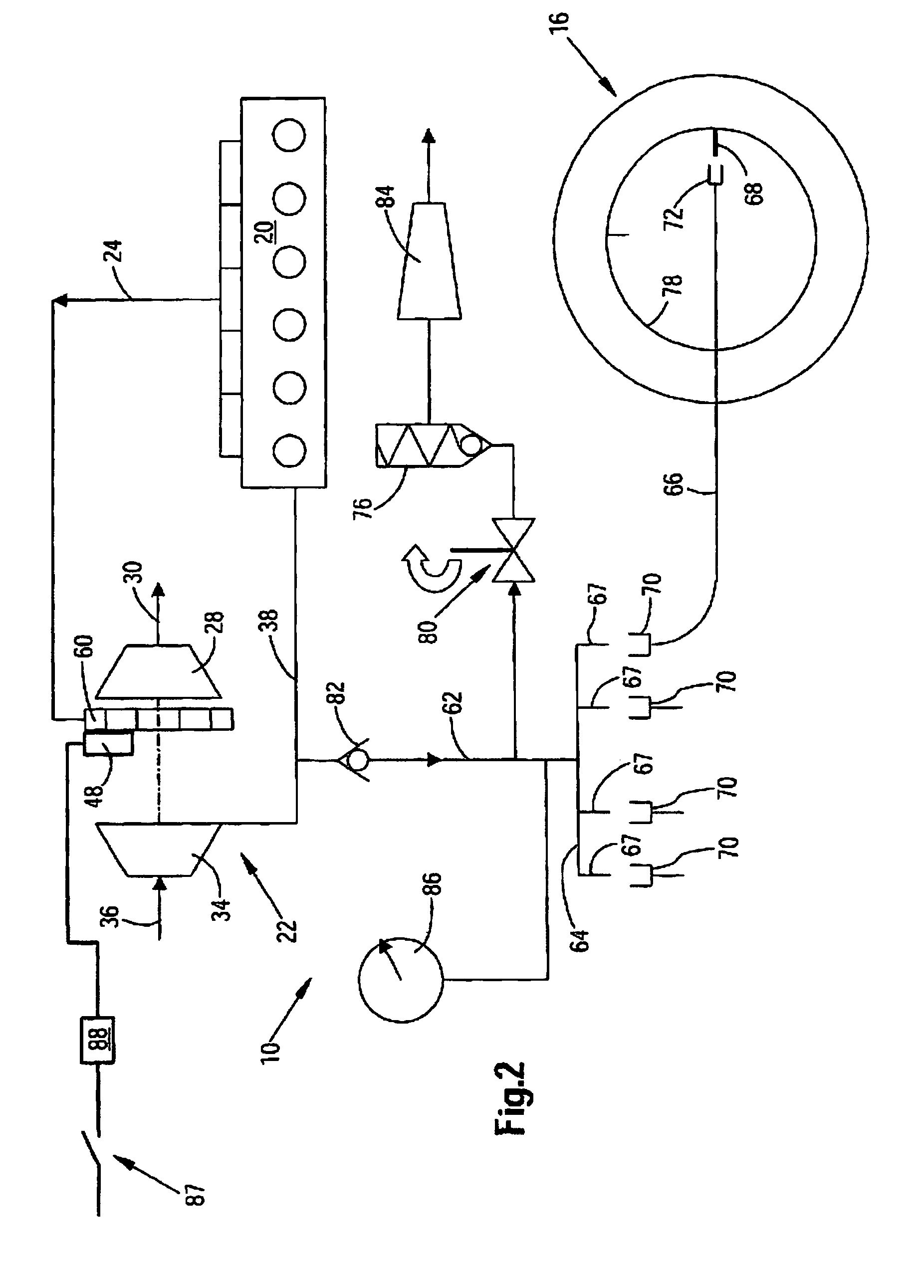
[0046]The tire-pressure regulating system 10 shown in the right hand part of FIG. 1 contains a distributing line 11, also called a pressure line, which is connected via a rotary transmission leadthrough 12 and an associated valve 14 to the four tires 16 of a work vehicle not shown in more detail. The rotary transmission leadthroughs 12 and valves 14 can be formed in typical ways. For example, the valves 14 can be directional control valves. Another valve arrangement mounted before the leadthroughs can also be provided for preparing the supply pressure, which, however, was not shown because it is not the subject matter of the present invention. In the pressure line 11, there is a pressure measurement point 18.

[0047]In the left hand part of the figure, a combustion engine 20 is shown which is equipped with an exhaust gas turbocharger 22. The exhaust gas line 26 of the turbocharger 22 is attached to the connection angle 24 of the combustion engine 20. The exhaust gas turbine 28 of the ...


PUM


Abstract

The invention relates to a system for regulating the pressure of tires mounted on a vehicle. The vehicle has an engine with a turbocharger which is a compressed air source for the pressure regulating system. The turbocharger has a variable geometry in order to supply a sufficiently high pressure.

Description

FIELD OF THE INVENTION[0001]The invention relates to a tire-pressure regulating system for setting the pressure of the tires mounted on a vehicle. The tire-pressure regulating system comprises, among other things, a compressed-air source. The vehicle has an internal combustion engine with a turbocharger, wherein the turbocharger is provided as the compressed-air source for the tire-pressure regulating system.BACKGROUND OF THE INVENTION[0002]Agricultural vehicles, in particular, such as tractors, combines, and trailers, as well as comparable vehicles, which are used on soft ground, are frequently equipped with large volume tires in order to achieve good terrain handling, good traction properties, and low ground pressure. Traction and ground pressure are especially low if low air pressure is set in the tires, so that in the field, operation with low tire pressure is preferred. However, with decreasing tire pressure, the carrying capacity of the tires decreases, and the rolling resista...

Claims


Application Information

Patent Timeline
Patent Type & Authority Patents(United States)
IPC IPC(8): F02D23/00B60C23/00B60C23/10B60C23/14B60K1/00B60K28/16B60K6/00F02B33/44F02B37/24
CPCB60C23/003F02B37/24F02B33/44Y02T10/144B60C23/00354B60C23/00372Y02T10/12
Inventor TARASINSKI, NICOLAISOBOTZIK, JOACHIMKNEER, BERNDGLASER, FRITZ
Owner DEERE & CO
Why Eureka
Try Eureka