Dummy fill method and system

A redundant metal and filling method technology, applied in the direction of instrumentation, design optimization/simulation, calculation, etc., can solve the problem of quickly completing redundant metal filling

Active Publication Date: 2017-09-12
INST OF MICROELECTRONICS CHINESE ACAD OF SCI
View PDF6 Cites 5 Cited by
  • Summary
  • Abstract
  • Description
  • Claims
  • Application Information

AI Technical Summary

Problems solved by technology

[0005] The present invention provides a method and system of a redundant metal filling method, which solves the problem that the redundant metal filling cannot be quickly completed without missing filling through the existing margin analysis technology

Method used


Image

  • Dummy fill method and system
  • Dummy fill method and system
  • Dummy fill method and system

Examples


Embodiment Construction

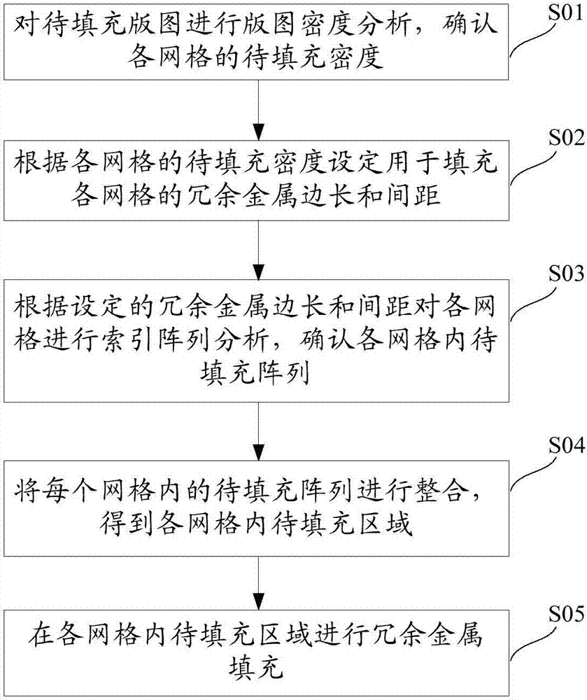
[0075] Embodiments of the present invention are described in detail below, examples of which are shown in the drawings, wherein the same or similar reference numerals designate the same or similar elements or elements having the same or similar functions throughout. The embodiments described below by referring to the figures are exemplary only for explaining the present invention and should not be construed as limiting the present invention. Furthermore, the present invention may repeat reference numerals and / or letters in different instances. This repetition is for the purpose of simplicity and clarity and does not in itself indicate a relationship between the various embodiments and / or arrangements discussed.

[0076] There are mainly two algorithms for margin analysis techniques of existing redundant metal filling methods, array index algorithm and scan line algorithm. Among them, the array index algorithm has a fast calculation speed, but because the array size is heavily...


PUM


Abstract

The invention provides a dummy fill method and system. The method includes the steps that layout density analysis is conducted on a to-be-filled layout, and the fill density of grids is determined; the side length and spacing of dummy metal for filling the grids are set according to the fill density of the grids; index array analysis is conducted on the grids according to the set side length and spacing of the dummy metal, and to-be-filled arrays in the grids are determined; the to-be-filled arrays in the grids are integrated to obtain to-be-filled areas in the grids; dummy fill is conducted on the to-be-filled areas in the grids. Due to the fact that index array analysis is conducted on the grids according to the set side length and spacing of the dummy metal and the to-be-filled arrays are integrated to obtain the to-be-filled areas, dummy fill can be rapidly completed without fill omission.

Description

technical field [0001] The invention relates to the field of semiconductor manufacturing, in particular to a method and system of a redundant metal filling method. Background technique [0002] With the continuous development of semiconductor technology, semiconductor process nodes are becoming smaller and smaller, and chemical mechanical polishing (CMP) is used for global planarization, which becomes more and more important. During the manufacturing process of the CMP process, since metals and oxides and other media have different material properties, they have different material removal rates during the CMP process, resulting in dishing and erosion defects. A butterfly defect is the difference in thickness between the dielectric layer in the blank area and the metal in the trench. Erosion defects refer to the thinning of the oxide and metal in the pattern area, which is the difference in the thickness of the oxide layer before and after polishing. The prior art eliminate...

Claims


Application Information

Patent Timeline
Patent Type & Authority Applications(China)
IPC IPC(8): G06F17/50
CPCG06F30/20G06F30/392G06F2119/18
Inventor 曹鹤陈岚孙艳张贺
Owner INST OF MICROELECTRONICS CHINESE ACAD OF SCI
Why Eureka
Try Eureka