Mass rate attenuator

a mass spectrometer and attenuator technology, applied in the field of mass spectrometer, can solve the problems of momentary signal loss, mass spectrometer cannot tolerate a large analyte mass rate, etc., and achieve the effect of quick filling and quick filling of the aliquot passag

Inactive Publication Date: 2005-05-10
IDEX HEALTH & SCI
View PDF41 Cites 29 Cited by
  • Summary
  • Abstract
  • Description
  • Claims
  • Application Information

AI Technical Summary

Benefits of technology

[0006]In one mass transfer module, there is a single interface between the stator and shuttle. The first and second primary passages merge at a bypass region that is open to the interface. This allows a large flow between the primary and secondary passages without requiring such flow to pass through the aliquot passage, while allowing such flow to quickly fill the aliquot passage. The aliquot passage can be formed by a groove in the face of the shuttle, so it can be quickly filled.

Problems solved by technology

The analyte mass rates that flow from a preparative chromatographic column are inherently large, but the mass spectrometer does not tolerate a large analyte mass rate.
A large mass rate can result in a lingering or tailing signal that distorts the results of a mass spectrometer, and a large mass rate can change the dielectric properties of the system and cause a momentary loss of signal.

Method used


Image

  • Mass rate attenuator
  • Mass rate attenuator
  • Mass rate attenuator

Examples


Embodiment Construction

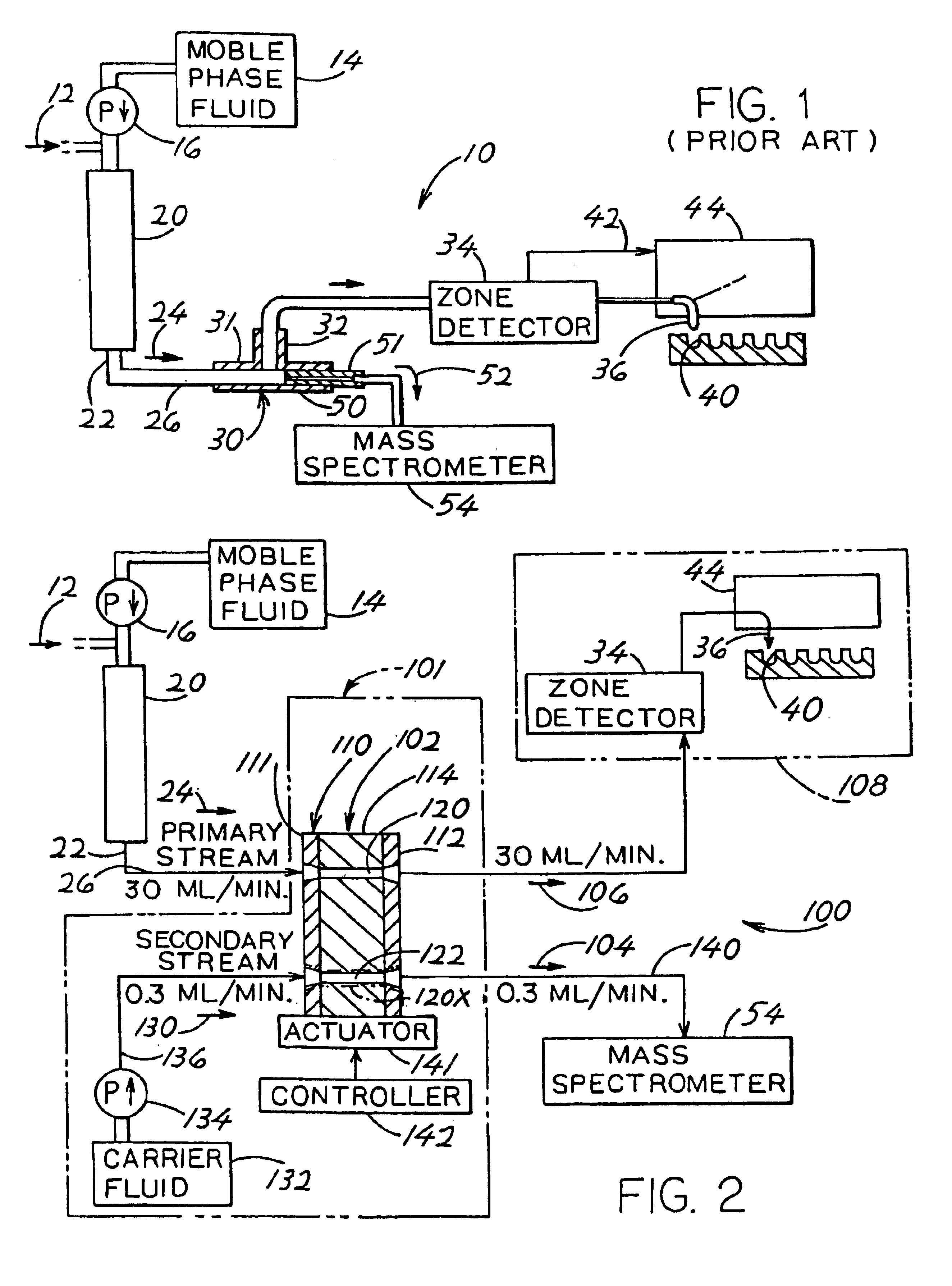
[0021]FIG. 1 shows a prior art separating and analyzing system 10 in which a sample 12 with components to be separated, is injected into a stream of mobile phase fluid emanating from a source 14 and pump 16 and flowed into a preparatory chromatographic column 20. The fluid passing through the column is separated by the column into compounds, or components, of different molecular weights. The output 22 of the column is a primary stream 24 that passes along a tube 26 into a first leg 31 of a Tee connector 30. A second leg 32 of the connector carries almost all of the fluid passing along the primary stream, to a zone detector 34. The zone detector 34, which may be an ultraviolet detector, detects when zones containing different compounds pass through it. The flow through the zone detector passes through a nozzle 36 which deposits the sample into a selected one of many containers 40. Whenever the zone detector detects a new compound, it delivers a signal along line 42 to a positioner 44...


PUM

PropertyMeasurementUnit
flow rateaaaaaaaaaa
flow rateaaaaaaaaaa
volumeaaaaaaaaaa

Abstract

While a large primary stream (24) of analytes flow from a chromatographic column (20) to containers of a receiver (108), small samples of the analytes are diverted for flow to a mass spectrometer (54) for analysis, by use of a transfer module (102). The transfer module includes a stator (110) and a rotor or shuttle (114). The shuttle has an aliquot passage (120) that initially lies in a first position where the primary stream flows through it so the aliquot passage receives a small sample. The shuttle then moves to a second position where the aliquot passage (at 122) is aligned with a pump (134) that pumps fluid out of the aliquot passage to the mass spectrometer.

Description

CROSS-REFERENCE TO RELATED APPLICATION[0001]Applicant claims priority from Provisional Patent Application No. 60 / 199,748 filed Apr. 26, 2000.BACKGROUND OF THE INVENTION[0002]A mixture of compounds, or analytes, can be separated by pumping the mixture through a separating device such as a chromatographic column. The outflow from the column may continue for perhaps several minutes, during which analytes of different molecular weights flow out at different times. Each analyte may flow out for a period such as a fraction of a minute. The analytes are delivered to a receiver where each analyte is stored in a separate container. At the same time as the column output is flowed to the receiver, a small amount of the column outlet is flowed to a mass spectrometer which indicates the molecular weight of each analyte. A prime use for the invention is to facilitate the purification of a synthesized compound during the development of a new drug. The products of the synthesis includes the desired...

Claims


Application Information

Patent Timeline
Patent Type & Authority Patents(United States)
IPC IPC(8): H01J49/02H01J49/04
CPCH01J49/04Y10T436/2575
Inventor NICHOLS, JON A.FOSTER, MARC D.
Owner IDEX HEALTH & SCI
Why Eureka
Try Eureka