Valve assembly for pressurized dispensers

a valve assembly and dispenser technology, applied in the direction of liquid handling, packaging goods types, transportation and packaging, etc., can solve the problems of reducing the robustness and reliability of the valve assembly, affecting the spray characteristics of the dispenser, and increasing production costs, so as to achieve faster filling and increase the flow rate

Active Publication Date: 2011-06-14
SC JOHNSON & SON INC
View PDF57 Cites 26 Cited by
  • Summary
  • Abstract
  • Description
  • Claims
  • Application Information

AI Technical Summary

Benefits of technology

[0013]This disclosure is directed toward a flow-modulating valve assembly for use in a pressurized dispenser. During filling, the product may be charged through one or more primary flow passages and one or more secondary flow passages into the dispenser, thereby achieving an increased flow rate for faster filling. During dispensing, on the other hand, the product may be dispensed through the one or more primary passages only, and not through the one or more secondary passages, thereby retaining a regular flow rate for controlled dispensing of the product.
[0017]In one embodiment, in which the one or more primary openings are provided on the bottom and the one or more secondary openings are provided on the sidewall of the valve housing, the blocking member may include a slidable sleeve having a sidewall that at least partially engages the sidewall of the valve housing. During product filling, the blocking member may be positioned so that neither of the primary and secondary openings on the valve housing is blocked by the sleeve, thereby increasing the product flow rate during the filling process. Upon completion of product filling, the blocking member may be repositioned so that the one or more secondary openings on the sidewall of the valve housing are blocked by the sleeve, thereby allowing the product to be dispensed only through the one or more primary openings at a regular flow rate.

Problems solved by technology

However, the increased product flow may adversely affect the spray characteristics of the dispenser.
Nevertheless, additional product filling paths achieved in both of the aforementioned examples require the deformation of delicate structural components, which may increases the production cost and decrease the robustness and reliability of the valve assembly.

Method used


Image

  • Valve assembly for pressurized dispensers
  • Valve assembly for pressurized dispensers
  • Valve assembly for pressurized dispensers

Examples


Embodiment Construction

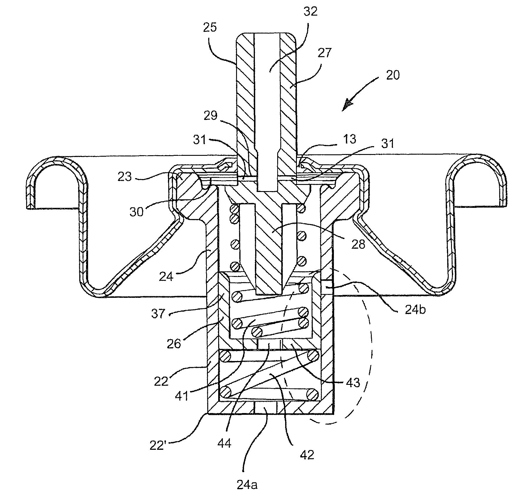
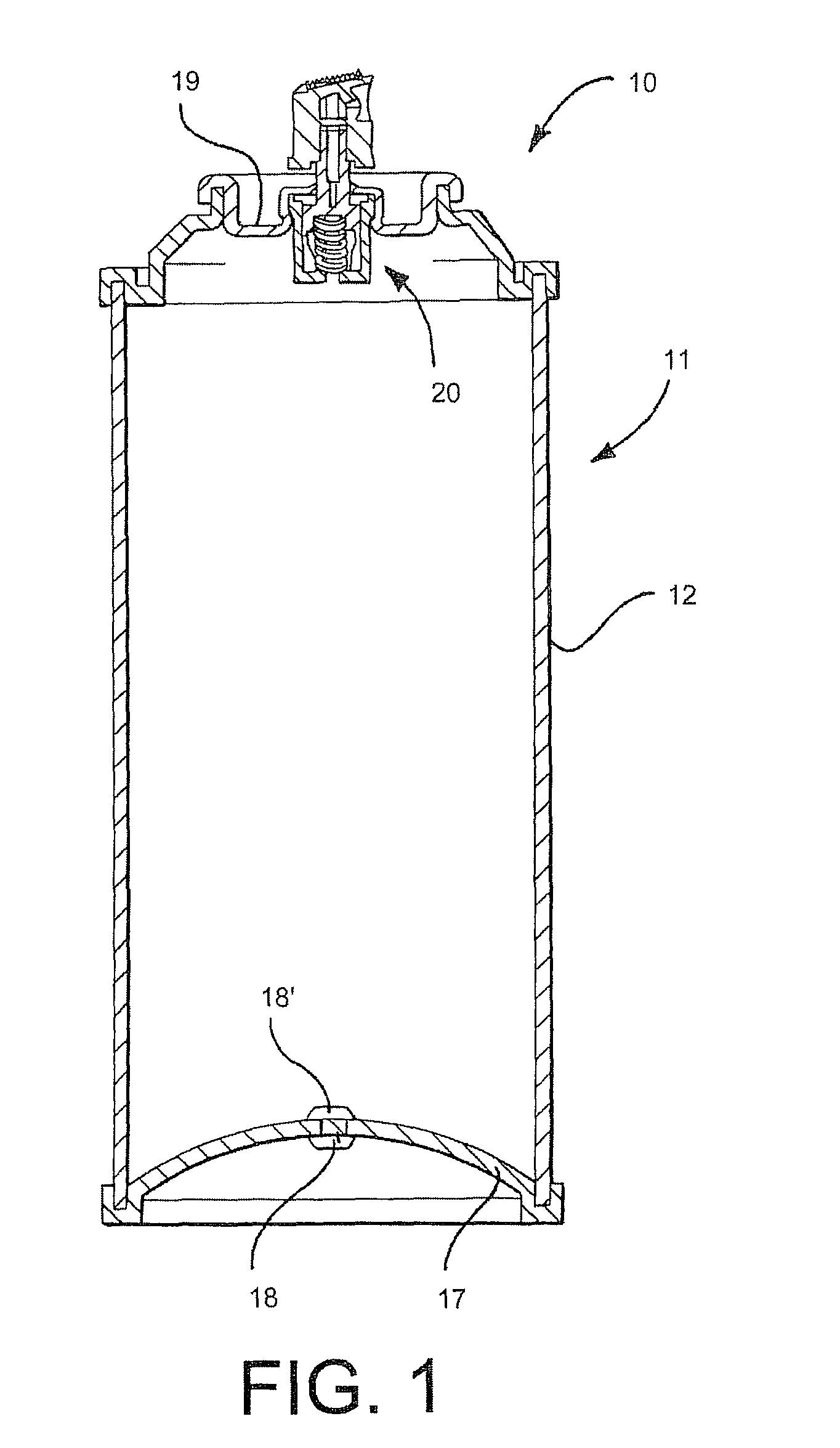
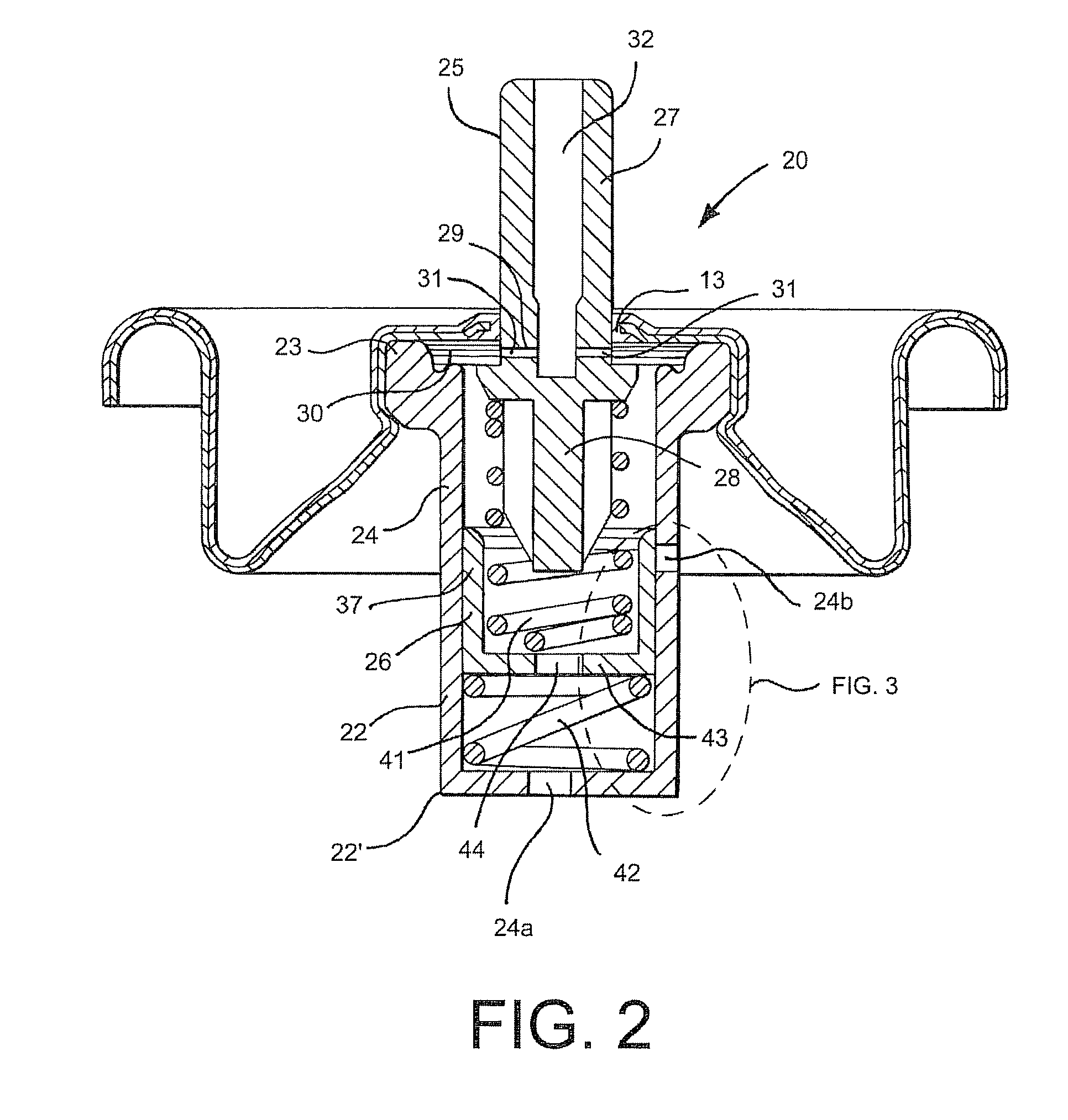
[0038]Referring now to the drawings, and with specific reference to FIG. 1, a conventional pressurized dispenser is generally referred to as reference numeral 10. While the dispenser 10 may be an aerosol dispenser, and have the type of actuator depicted, it is to be understood that this is but one example of the types of the dispensers in which the valve assembly of the present disclosure can be employed. Again with reference to the pressurized dispenser 10, it is shown to include a container 11 having a cylindrical wall 12 formed of a flat piece of sheet metal. Attached to the bottom edge of the sidewall 12 is a bottom wall 17, which may have an optional center charging orifice 18, through which a propellant may be charged into the container 11. The charging orifice 18 may be closed by a resilient plug 18′ after the propellant is charged. Crimped to the top edge of the side wall 12 is a mounting cup 19 having a large center opening, through which a valve assembly 20 is inserted. A ...


PUM

PropertyMeasurementUnit
permeation resistantaaaaaaaaaa
forceaaaaaaaaaa
vapor pressureaaaaaaaaaa

Abstract

An improved valve assembly for use in a pressurized dispenser is disclosed. The disclosed valve assembly may include a valve housing and a blocking member operatively associated with the valve housing, wherein the wall of the valve housing includes at least one transverse primary opening and at least one transverse secondary opening thereon. The blocking member is slidable from a filling position, in which fluid communication between the interior and exterior of the valve housing is established through both primary and secondary openings, to a dispensing position, in which fluid communication between the interior and exterior of the valve housing is established only through the primary opening and not through the secondary opening. The blocking member may include a slidable sleeve, a slidable piston plate, or a combination of both. In operation, the disclosed valve member may provide an increased flow rate during product and / or propellant filling while retaining a regular flow rate during dispensing.

Description

BACKGROUND OF THE DISCLOSURE[0001]1. Technical Field[0002]An improved valve assembly for use in a pressurized dispenser is disclosed. The valve member provides faster product and / or propellant filling. The disclosed valve assembly may include a valve housing and a blocking member disposed within the valve housing, wherein the valve housing includes at least one transverse primary opening and at least one transverse secondary opening thereon. The blocking member is movable from a filling position, in which the product and / or propellant may be charged into the dispenser through both the primary and secondary openings, to a dispensing position, in which the product and / or propellant may be dispensed from the dispenser only through the primary opening and not through the secondary opening.[0003]2. Description of the Related Art[0004]Pressurized dispensers have been commonly used to store and dispense personal, household, industrial, and medical products, and provide a low cost, easy to ...

Claims


Application Information

Patent Timeline
Patent Type & Authority Patents(United States)
IPC IPC(8): B65D83/00
CPCB65D83/425B65D83/48
Inventor MILLER, ALLEN D.SAMUELSON, LEON C.
Owner SC JOHNSON & SON INC
Why Eureka
Try Eureka