Method for filling non self-intersecting polygon in FPGA

A filling method and polygonal technology, which is applied in the field of FPGA data processing, can solve problems such as inability to directly fill concave polygons, complex sorting of filling algorithms, and long sorting time, and achieve the effects of reducing sorting calculations, fast filling speed, and reducing time costs

Inactive Publication Date: 2017-05-10
ADVANCED DIGITAL SCREEN SYST INC
View PDF4 Cites 6 Cited by
  • Summary
  • Abstract
  • Description
  • Claims
  • Application Information

AI Technical Summary

Problems solved by technology

[0006] The purpose of the present invention is to provide a fast method for filling arbitrary polygons in the FPGA for the shortcomings of complex sorting, large resource consumption and long sorting time in the existing FPGA filling algorithm, and the shortcomings that the existing FPGA-based filling algorithm cannot directly fill concave polygons. Methods for non-self-intersecting polygons

Method used


Image

  • Method for filling non self-intersecting polygon in FPGA
  • Method for filling non self-intersecting polygon in FPGA
  • Method for filling non self-intersecting polygon in FPGA

Examples


Embodiment 1

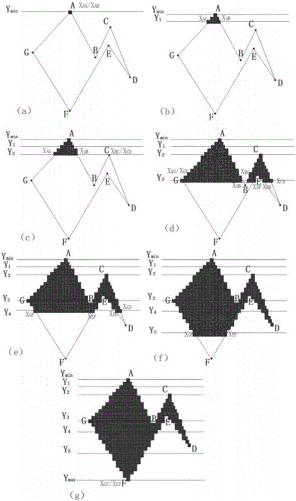
[0044] attached figure 2 (a) is the polygon ABCDEFG to be filled in the present embodiment, and the filling method process of this polygon is as follows:

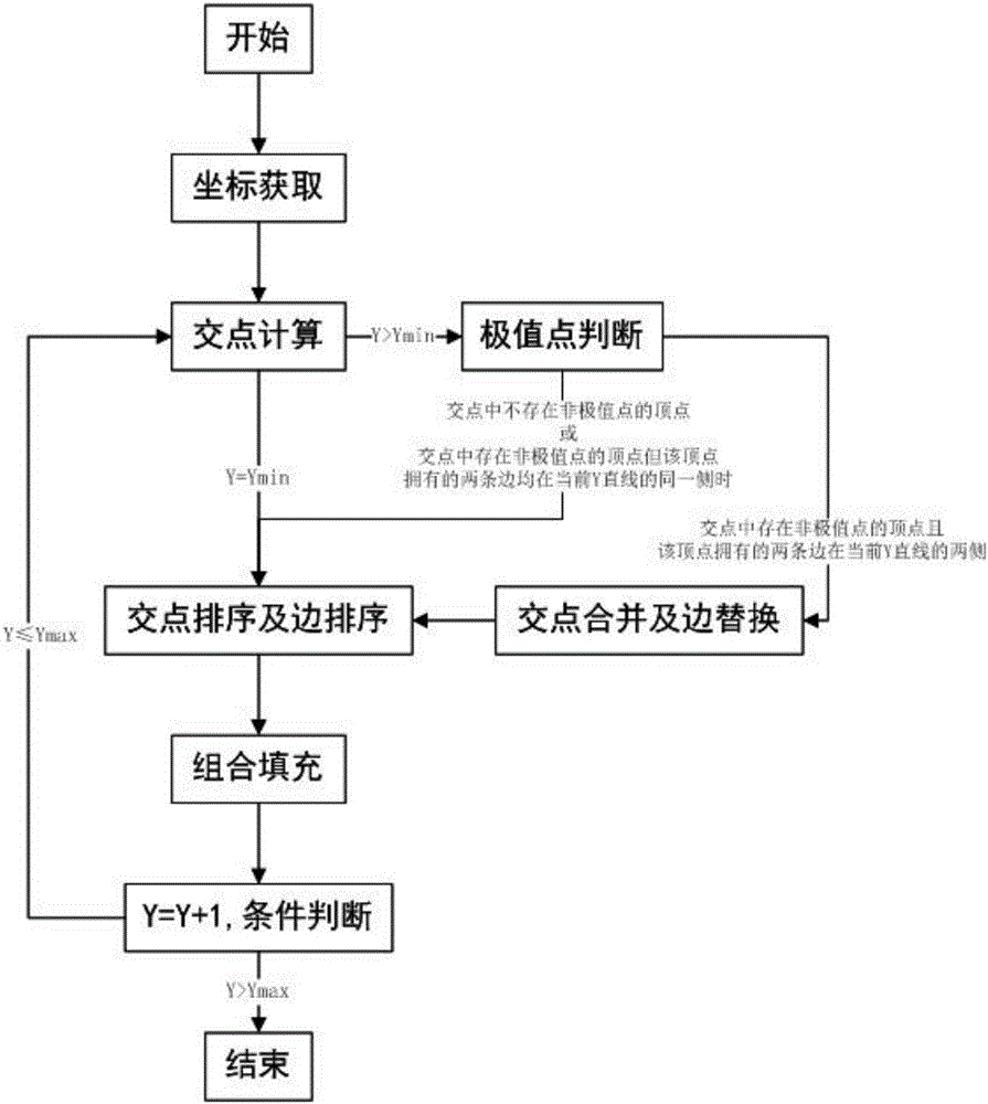
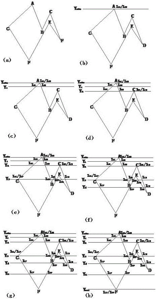
[0045](1) Coordinate acquisition. Obtain the maximum value, minimum value and non-extreme points of the Y coordinate values ​​of each vertex of the polygon ABCDEFG, such as figure 2 As shown in (a), point A is the minimum value point, namely ; Point F is the maximum value point, namely . Points B, C, D, E, and G are non-extreme points. Number the sides of the polygon ABCDEFG, denoted as AB, BC, CD, DE, EF, FG, GA.

[0046] (2) Intersection calculation. calculate The intersection of the straight line and the polygon ABCDEFG, such as figure 2 As shown in (b), the intersection points are and , the number of intersection points is 2, and the sides where the intersection points are located are AG and AB.

[0047] (3) Intersection sorting and edge sorting. Compare and the size of the value, , so the orde...


PUM


Abstract

The present invention discloses a method for filling a non self-intersectig polygon in a FPGA. The filling method comprises the steps of coordination acquisition, intersection point calculation, intersection point ranking and edge ranking, combination filling, and condition determining. Compared with the existing algorithms, the method has a simple filling process and has high filling speed. Particularly, in the ranking algorithm in the filling method, a simplified ranking method is adopted according to change of the number of the intersection points, so that the ranking calculation amount of the intersection points in filling is greatly reduced, and the filling speed is improved remarkably.

Description

technical field [0001] The invention relates to the technical field of FPGA data processing, in particular to a fast filling algorithm for rasterizing vector data of a lithography machine. Background technique [0002] Laser direct imaging (laser direct imaging, LDI for short), also known as laser direct writing, is a technology developed in recent years for the production of semiconductor devices. The traditional exposure process is to transfer the image to the substrate by irradiating the film with a mercury lamp, while the LDI uses a laser scanning method to directly image the image on the substrate through a pattern generator. Compared with the traditional exposure technology, the LDI exposure process does not require film, which effectively reduces the cost, and has a simple process and high image precision, which can adapt to finer graphic exposure and is also conducive to improving the yield of production. [0003] Usually, the graphics data designed for semiconducto...

Claims


Application Information

Patent Timeline
Patent Type & Authority Applications(China)
IPC IPC(8): G06T11/40G06T1/20
CPCG06T11/40G06T1/20
Inventor 陈修涛韩非王运钢董辉吴景舟
Owner ADVANCED DIGITAL SCREEN SYST INC
Why Eureka
Try Eureka