Injection molding device

A technology of injection molding and cavity molding, which is applied in optics, instruments, light guides, etc., and can solve problems such as stress imbalance, long time, and cost of filling the molding cavity.

Inactive Publication Date: 2010-11-17
HONG FU JIN PRECISION IND (SHENZHEN) CO LTD +1
View PDF6 Cites 6 Cited by
  • Summary
  • Abstract
  • Description
  • Claims
  • Application Information

AI Technical Summary

Problems solved by technology

The molding machine with this structure not only makes filling the molding cavity more time-consuming, but also often makes the thin end complete with filling while the thick end continues to have material entering the thick end, which causes the material at the thin end to stand still and start to solidify, making the thick end and the thick end Unbalanced stress at the thin end affects the performance of the light guide plate

Method used


Image

  • Injection molding device
  • Injection molding device
  • Injection molding device

Examples


Embodiment Construction

[0012] The present invention will be further described in detail below in conjunction with the accompanying drawings.

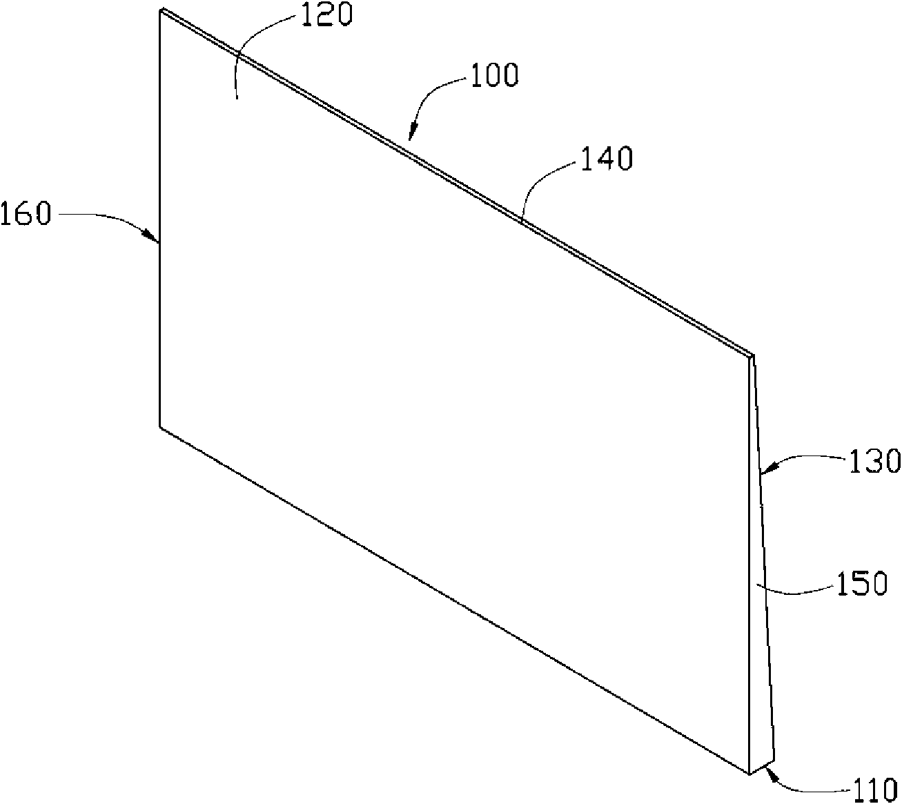
[0013] see figure 1 , the wedge-shaped light guide plate 100 has a light incident surface 110, a light exit surface 120 connected to the light incident surface 110, a bottom surface 130 opposite to the light exit surface 120, a first side 140 opposite to the light incident surface 110, and a light incident surface 110 connected And the opposite second side 150 and third side 160 .

[0014] The width of the second side 150 and the third side 160 gradually decreases from the light incident surface 110 to the first side 140, so that the thickness of the light incident surface 110 is greater than the thickness of the first side 140, that is, the light incident surface 110 is the thick end, the second One side 140 is a thin end.

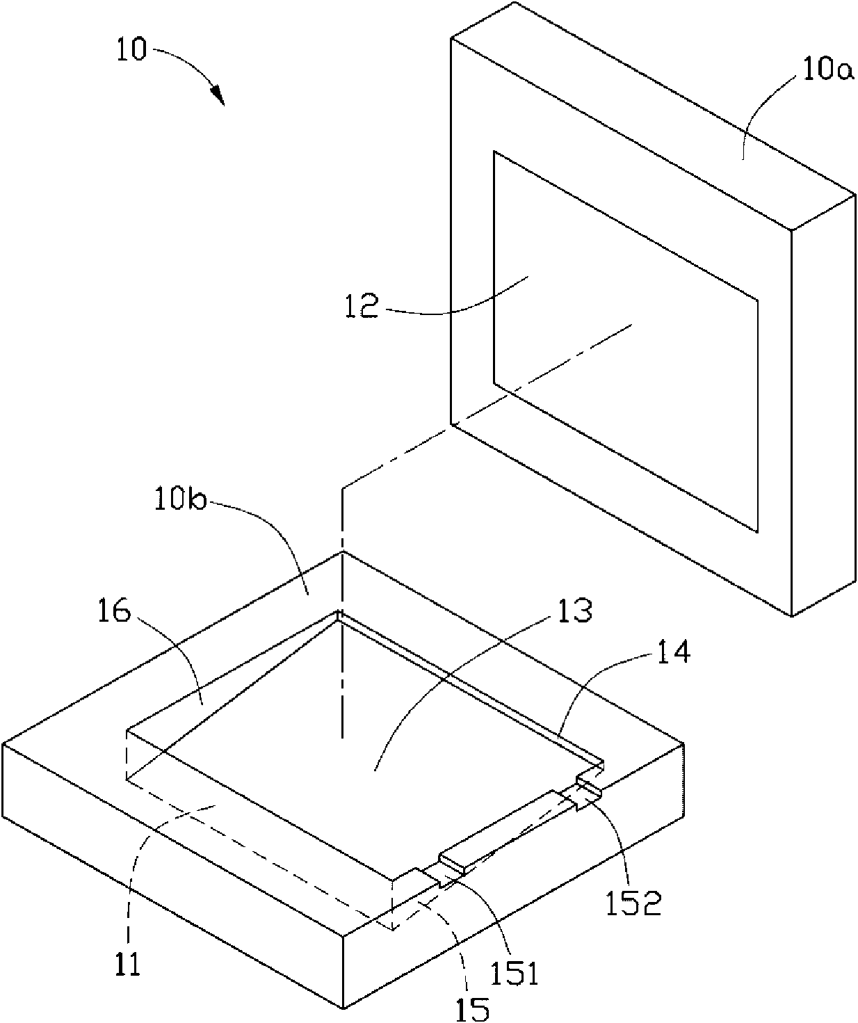
[0015] Such as figure 2 As shown, the injection molding device 10 for manufacturing the wedge-shaped light guide plate 100 provided...


PUM


Abstract

The invention relates to an injection molding device, which comprises a molding chamber. The molding chamber is used for manufacturing a wedge-shaped light guide plate which comprises a light incoming surface, a light outgoing surface connected with the light incoming surface, a first side face opposite to the light incoming surface, two second side faces connected with and opposite to the light incoming surface, and a bottom surface opposite to the light outgoing surface; the width of the second side faces is reduced gradually from the light incoming surface to the first side face; the molding chamber is provided with a first inner wall corresponding to the light incoming surface, a second inner wall corresponding to the light outgoing surface, a third inner wall corresponding to the bottom surface, a fourth inner wall corresponding to the first side face, and two fifth inner walls corresponding to the two second side faces; at least one of the fifth inner walls is provided with a first sprue and a second sprue which are used for filling the molding material for the light guide plate; and the distance between the position of the first sprue and the first inner wall is less than that between the position of the second sprue and the second inner wall.

Description

technical field [0001] The invention relates to a device for manufacturing a light guide plate, in particular to an injection molding device for manufacturing a wedge-shaped light guide plate. Background technique [0002] The backlight module is mainly used as the light source system of the liquid crystal display. Its working principle is: the light emitted by the point light source or the line light source enters the light guide plate and propagates through the bottom surface of the light guide plate with optical structure design and the reflector, so that the light is diffused and emitted. Evenly distributed in the light-emitting area to meet the optical characteristics of liquid crystal displays. [0003] The light guide plate is an indispensable key component in the backlight module, and its shape and material composition determine the overall brightness of the backlight module. When an injection molding machine is used to manufacture a wedge-shaped light guide plate, ...

Claims


Application Information

Patent Timeline
Patent Type & Authority Applications(China)
IPC IPC(8): B29C45/03B29C45/27G02B6/00B29L11/00
CPCG02B6/0046G02B6/0065B29C45/0025B29C45/0046B29C2045/0027
Inventor 吴锡章
Owner HONG FU JIN PRECISION IND (SHENZHEN) CO LTD
Why Eureka
Try Eureka