Reinforcing element and method for producing a reinforcing element

A technology of reinforcing elements and reinforcing pads, which is applied in the field of manufacturing components, can solve the problems of time-consuming manufacturing of reinforcing elements and the danger of shell expansion, etc., and achieve the effect of small weight

Inactive Publication Date: 2017-05-31
胡贝特拉佩斯托费尔
View PDF5 Cites 5 Cited by
  • Summary
  • Abstract
  • Description
  • Claims
  • Application Information

AI Technical Summary

Problems solved by technology

[0003] The embodiments known from the general prior art have the disadvantage that the reinforcing elements are time-consuming to manufacture and that at least one shell of the double-walled structure provided with the reinforcing elements is exposed to the risk of expansion.

Method used


Image

  • Reinforcing element and method for producing a reinforcing element
  • Reinforcing element and method for producing a reinforcing element
  • Reinforcing element and method for producing a reinforcing element

Examples


Embodiment Construction

[0071] At the outset, it should be pointed out that in the different described embodiments, identical parts are provided with the same reference symbols or the same component designations, wherein the disclosure contained in the entire description can be transferred to the reference symbols with the same reference symbols. Or on the same part with the same component name. Positional indications selected in the description, such as top, bottom, sideways, etc., also refer to the directly described and illustrated figures and, in the event of a change in position, are carried over to the new position.

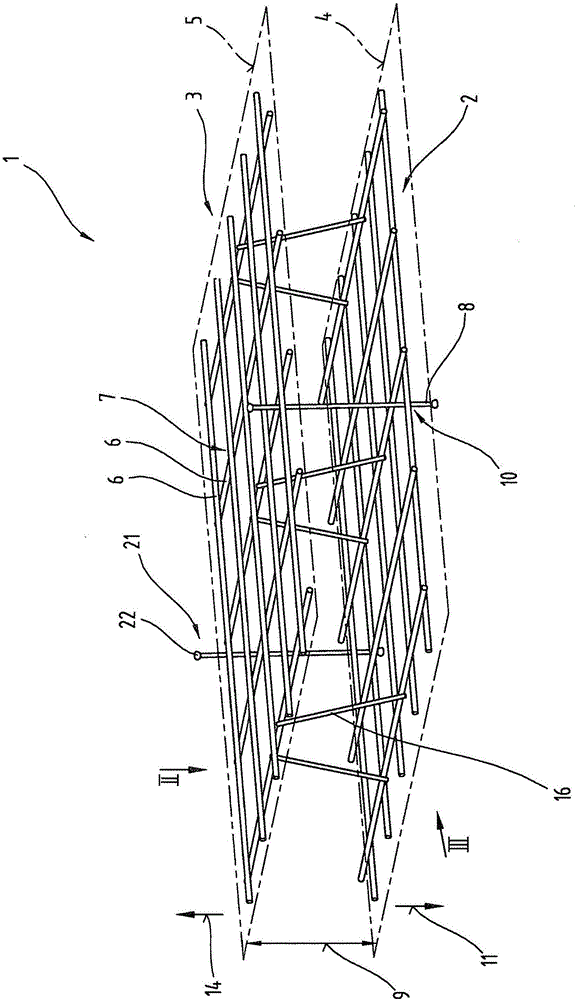
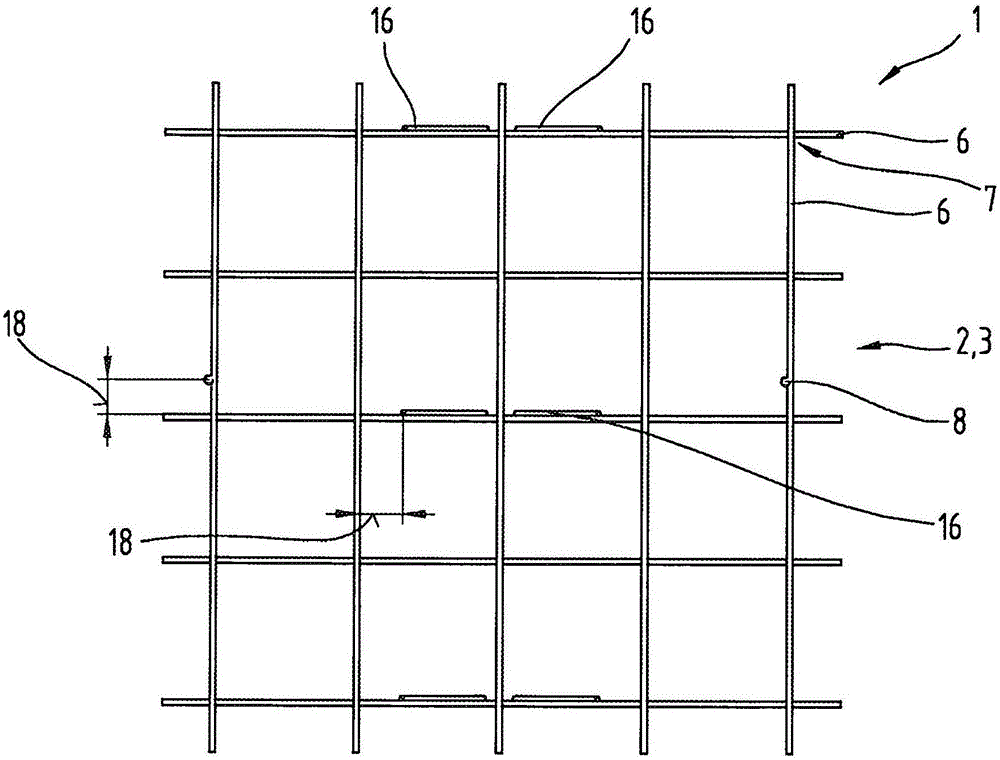
[0072] figure 1 The exemplary reinforcing element 1 according to the invention is shown in a perspective view. figure 2 and image 3 shows the reinforcement element 1 in accordance with figure 1 The top view of II and follow the figure 1 Side view of III in , wherein the same reference numerals or component designations are used for the same parts as in the respective precedi...


PUM

PropertyMeasurementUnit
thicknessaaaaaaaaaa

Abstract

The invention relates to a reinforcing element (1), comprising a first reinforcing mat (2) and a second reinforcing mat (3) having metal mat rods (6), which are welded at angles to each other at junction points (7), which reinforcing mats (2, 3) are held spaced apart from each other at a normal distance (9) by rod-shaped spacers (8) with respect to the first mat plane (4) and the second mat plane (5) of the reinforcing mats. The spacers (8) are metal and are permanently connected to individual mat rods (6) of the first reinforcing mat (2) and of the second reinforcing mat (3) by welding connections (10), preferably resistance welding connections, wherein at least individual spacers (8) protrude outward at least beyond the first mat plane (4) of the first reinforcing mat (2) in a direction (11) pointing away from the second reinforcing mat (3) by a first protrusion length. The invention further relates to a double wall equipped with the reinforcing element and to methods for producing the reinforcing element and the double wall.

Description

technical field [0001] The invention relates to a reinforcing element as well as to a double wall structure equipped with a reinforcing element and a method for producing the component, as specified in claims 1 , 14 and 15 . Background technique [0002] Stiffening elements of this type generally have a two-dimensional base element and intermediate elements for providing a three-dimensional structure. The intermediate element usually takes the form of a grid carrier In the form of a configuration in which the additional rod element protrudes from the two-dimensional base element and is connected thereto, and wherein the additional rod element is connected to the longitudinal rod on the side facing away from the base element. [0003] The embodiments known from the general prior art have the disadvantage that the reinforcing elements are time-consuming to manufacture and that at least one shell of the double-walled structure provided with the reinforcing elements is exposed...

Claims


Application Information

Patent Timeline
Patent Type & Authority Applications(China)
IPC IPC(8): B28B7/08B28B23/02E04B2/86
CPCE04C5/064B28B7/085B28B23/028E04B2/84E04B2/8617E04B2103/02E04B2103/06E04C2/044E04C5/168E04C5/18E04C2002/047E04C2002/048
Inventor 胡贝特·拉佩斯托费尔
Owner 胡贝特拉佩斯托费尔
Why Eureka
Try Eureka