
Device for the translation of a displacement of an actuator, in particular for an injection valve

Inactive Publication Date: 2006-07-18
CONTINENTAL AUTOMOTIVE GMBH
View PDF15 Cites 7 Cited by
  • Summary
  • Abstract
  • Description
  • Claims
  • Application Information

AI Technical Summary

Benefits of technology

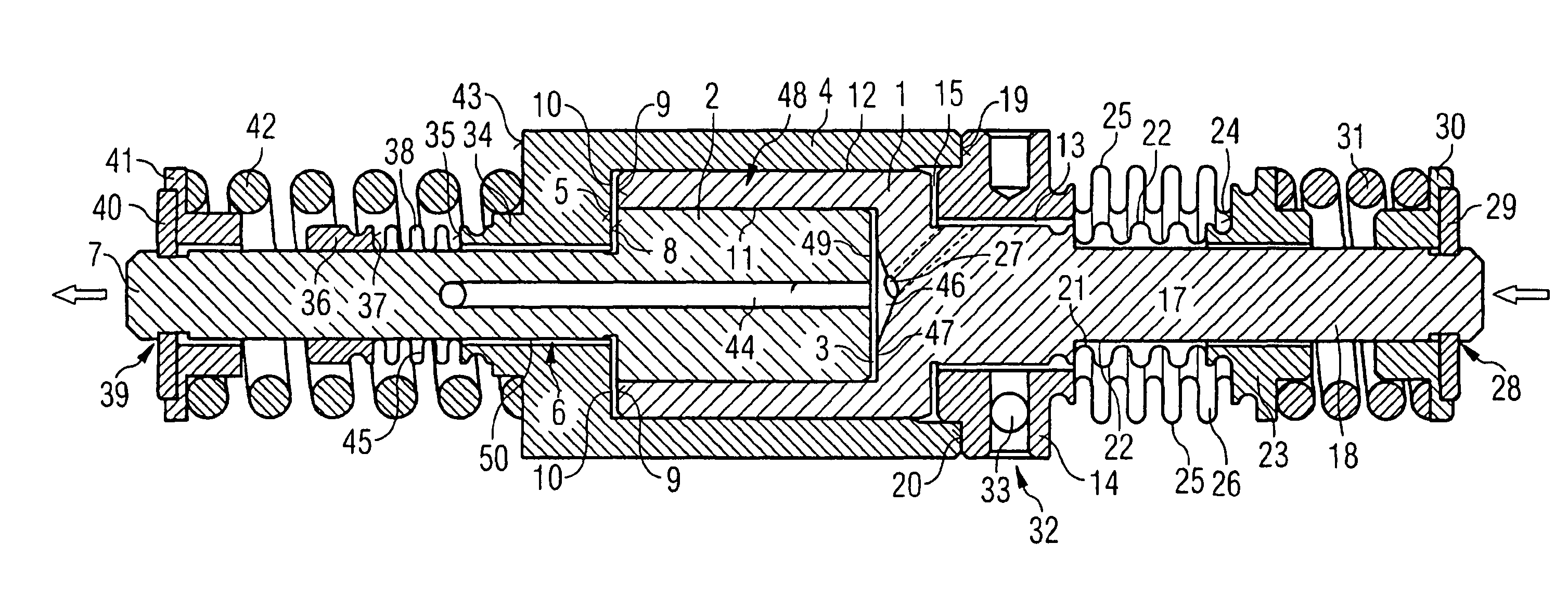
[0012]One advantage of the invention stems from the fact that the dead volume in the piston chamber is reduced. The advantage of the invention is achieved in that the tensioning element for pre-tensioning the second piston is arranged outside the piston chamber. Since the tensioning element is arranged outside the piston chamber, the piston chamber can be significantly smaller. Due to the smaller piston chamber, altogether greater dynamics are achieved in the translation of the motion of the first piston and on the second piston.
[0013]In a preferred embodiment of the invention the means of tensioning provided is a tensioning spring that is fixed between the housing and a supporting ring. The supporting ring is fastened to a piston rod of the second piston. The arrangement of a supporting ring provides a simple and reliable bearing surface for the tensioning spring.
[0014]Preferably the supporting ring takes the form of a sleeve in which a supporting rim is formed. The tensioning spring grips the supporting rim. The supporting ring is connected to the piston rod by means of a locking plate. Using a sleeve-shaped supporting ring prevents the tensioning spring from becoming misshapen. In addition the fashioning of a supporting rim provides a secure bearing surface for the tensioning spring. Furthermore the use of a locking plate is a safe and simple technique for connecting the supporting ring and the piston rod. Reliable functioning of the translation device together with excellent long-term stability is thus achieved.
[0015]The preferred embodiment is provided with a second tensioning spring which is likewise arranged outside the piston chamber and is fixed between the housing and a piston rod of the first piston. Pre-tensioning of the first piston in the opposite direction to the pre-tensioning of the second piston is thus also achieved. By this means a starting position for the first piston is reliably defined. This therefore makes it among other things unnecessary for the first piston to be solidly connected to an actuator.
[0016]In a preferred embodiment the second tensioning spring is arranged outside the housing, where it is fixed between the first and second bellows and the piston rod of the first piston. By this means not only is the piston rod pre-tensioned but also a pressure is created in the equalization chamber bounded by the first and second bellows.
[0017]In a further preferred embodiment the piston chamber is hydraulically connected by means of a drill hole to a sealed area which is arranged outside the housing and preferably sealed by a bellows that is connected in leak-proof fashion around the housing and the second piston. By this means the piston chamber can be quickly emptied. In a further preferred embodiment the piston chamber is also hydraulically connected to the equalization chamber by means of a drill hole. This connection to the equalization chamber also enables the fluid to escape quickly from the piston chamber. These arrangements enable the first piston to move towards the second piston without any significant counter-force.

Problems solved by technology

Moreover the piston chamber has a relatively large dead volume.
The relatively large dead volume gives rise to adverse effects on the motional dynamics of the first and second pistons.

Method used


Image

  • Device for the translation of a displacement of an actuator, in particular for an injection valve
  • Device for the translation of a displacement of an actuator, in particular for an injection valve

Examples


Embodiment Construction

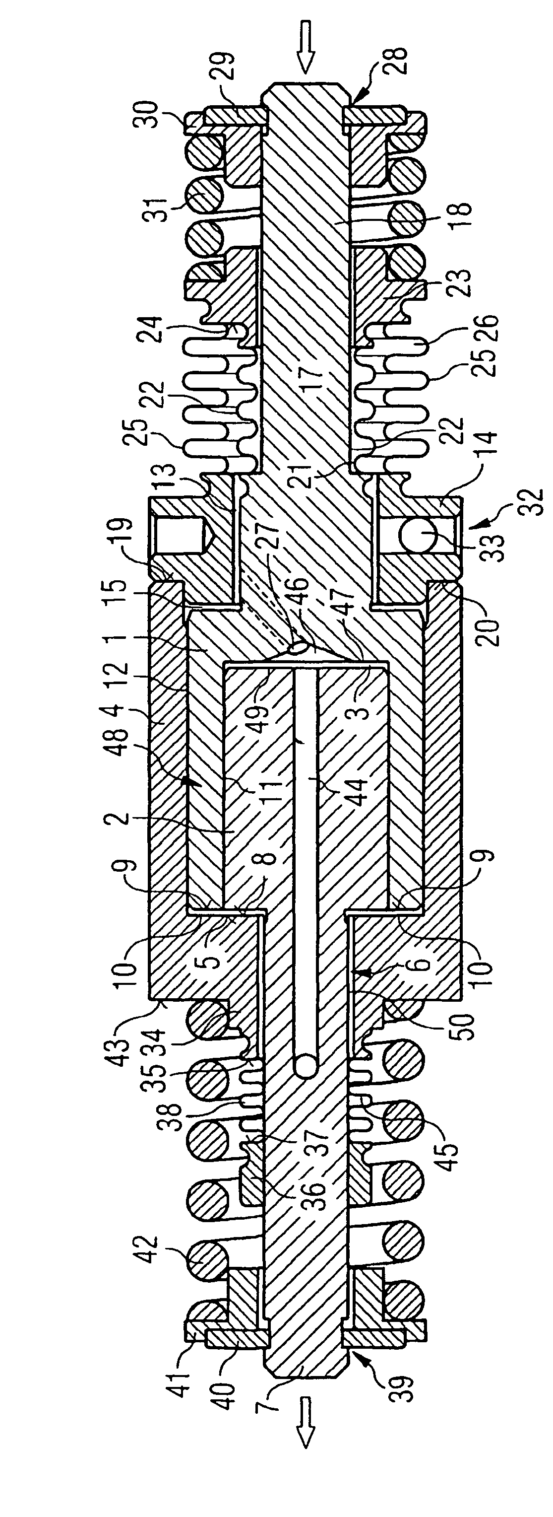
[0020]There is a first piston 1 in the form of a sleeve which is open at one end. The sleeve-shaped part of the piston forms a piston chamber 3 in which a second piston 2 is located. The first and second pistons 1, 2 form the boundaries of the piston chamber 3. The first piston 1 is itself located in a cylinder-shaped chamber 48 of a housing 4 which has an end surface 5 at the front end of the first piston 1. In the end surface 5 is an opening 6 through which a piston rod 7 of the second piston 2 is led. The piston rod 7 has a smaller diameter than the second piston 2. The piston rod 7 has a ring-shaped shoulder 8 and thus changes to the wider diameter of the second piston 2. A translation chamber 10 is formed between the end surface 5, the shoulder 8 and a ring-shaped front end 9 of the first piston 1. The translation chamber 10 is hydraulically connected to the piston chamber 3 by means of a first sealing gap 11 which is formed between a side wall of the second piston 2 and an inn...


PUM


Abstract

A device, for the translation of a displacement of an actuator, in particular for an injection valve, essentially comprises two counter-displaceable pistons, coupled together by means of a translational chamber in a play-free manner. The translation chamber is filled with a translation medium and is connected to an equalization chamber by means of a sealing gap. The sealing gap only equalizes pressure differences between the translation chamber and the equalization chamber which are of long duration. One of the two pistons is pre-tensioned in a starting position by means of an externally arranged spring. A reduction in the dead volume between the pistons is possible as a result of the arrangement of the spring outside the piston.

Description

CROSS REFERENCE TO RELATED APPLICATION[0001]This application is a continuation of copending International Application No. PCT / DE02 / 04465 filed Dec. 5, 2002 which designates the United States, and claims priority to German application no. 101 62 045.4 filed Dec. 17, 2001.TECHNICAL FIELD OF THE INVENTION[0002]The invention relates to a device for the translation of a displacement of an actuator.DESCRIPTION OF THE RELATED ART[0003]Injection valves such as piezoelectrically operated injection valves use an actuator with a relatively small control displacement. So that an injection needle or a servo valve for controlling an injection needle can be correctly actuated despite the small displacement of the piezoelectric actuator, it is necessary to translate the displacement of the actuator. Appropriate translation devices are used for this translation.[0004]A hydraulic device for the translation of an actuator displacement is known from document DE 19 962 177 A1. The device has a first pis...

Claims


Application Information

Patent Timeline
IPC IPC(8): F16K31/12F02M51/06F02M59/46F02M61/16F02M63/00
CPCF02M51/0603F02M61/167F02M2200/707F02M2200/705F02M2200/704
Inventor SCHURZ, WILLIBALD
Owner CONTINENTAL AUTOMOTIVE GMBH
Learn More