Flow path switching valve and high performance liquid chromatograph using the same

a switching valve and flow path technology, applied in the field of high-performance liquid chromatographs, can solve the problem of inability to analyze objects by a quality analyzer with high sensitivity, and achieve the effect of reducing the volume so far required by the pip

Inactive Publication Date: 2007-05-17
SHIMADZU CORP
View PDF1 Cites 17 Cited by
  • Summary
  • Abstract
  • Description
  • Claims
  • Application Information

AI Technical Summary

Benefits of technology

[0014] The present invention is directed to reduce the dead volume of the flow path with trap functions.
[0026] If the flow path switching valve of the present invention is applied to an HPLC with trap functions, the dead volume so far required by the pipe can be reduced in the HPLC.

Problems solved by technology

However, during the above period, the analyzed object condensed by the trap column 57 is diffused, and thus sometimes, it is impossible to analyze the object by a quality analyzer with high sensitivity.

Method used


Image

  • Flow path switching valve and high performance liquid chromatograph using the same
  • Flow path switching valve and high performance liquid chromatograph using the same
  • Flow path switching valve and high performance liquid chromatograph using the same

Examples


Embodiment Construction

[0031] An embodiment of the present invention is described below in detail.

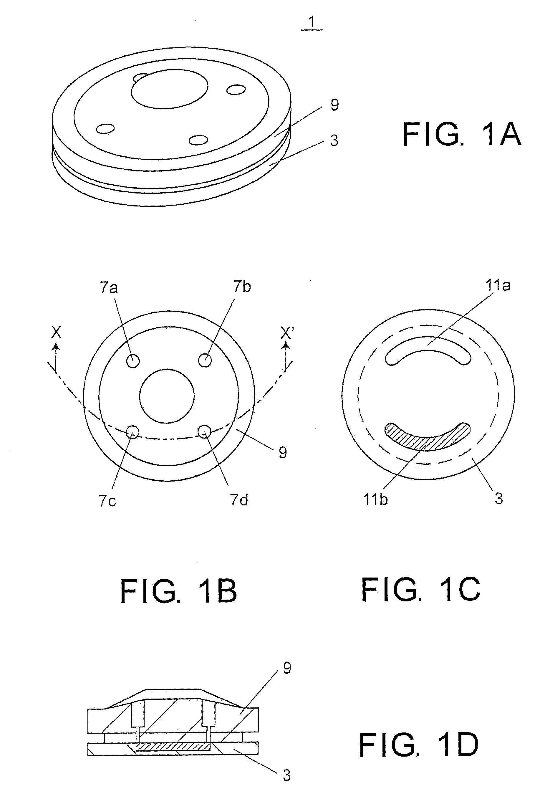
[0032]FIG. 1A˜1D show a flow path switching valve, wherein FIG. 1A is a perspective view of the flow path switching valve, FIG. 1B is a plan view of a housing top, FIG. 1C is a plan view of a rotor, and FIG. 1D is a vertical sectional view of FIG. 1B along the Line X-X′. The flow path switching valve 1 includes: a rotor for switching the flow paths, i.e., rotor 3, and a housing top 9 having the stator function of keeping the rotation of the rotor 3 liquid-tight. In this embodiment, in order to reduce the volume of the value 1, the housing top 9 also serves as a stator.

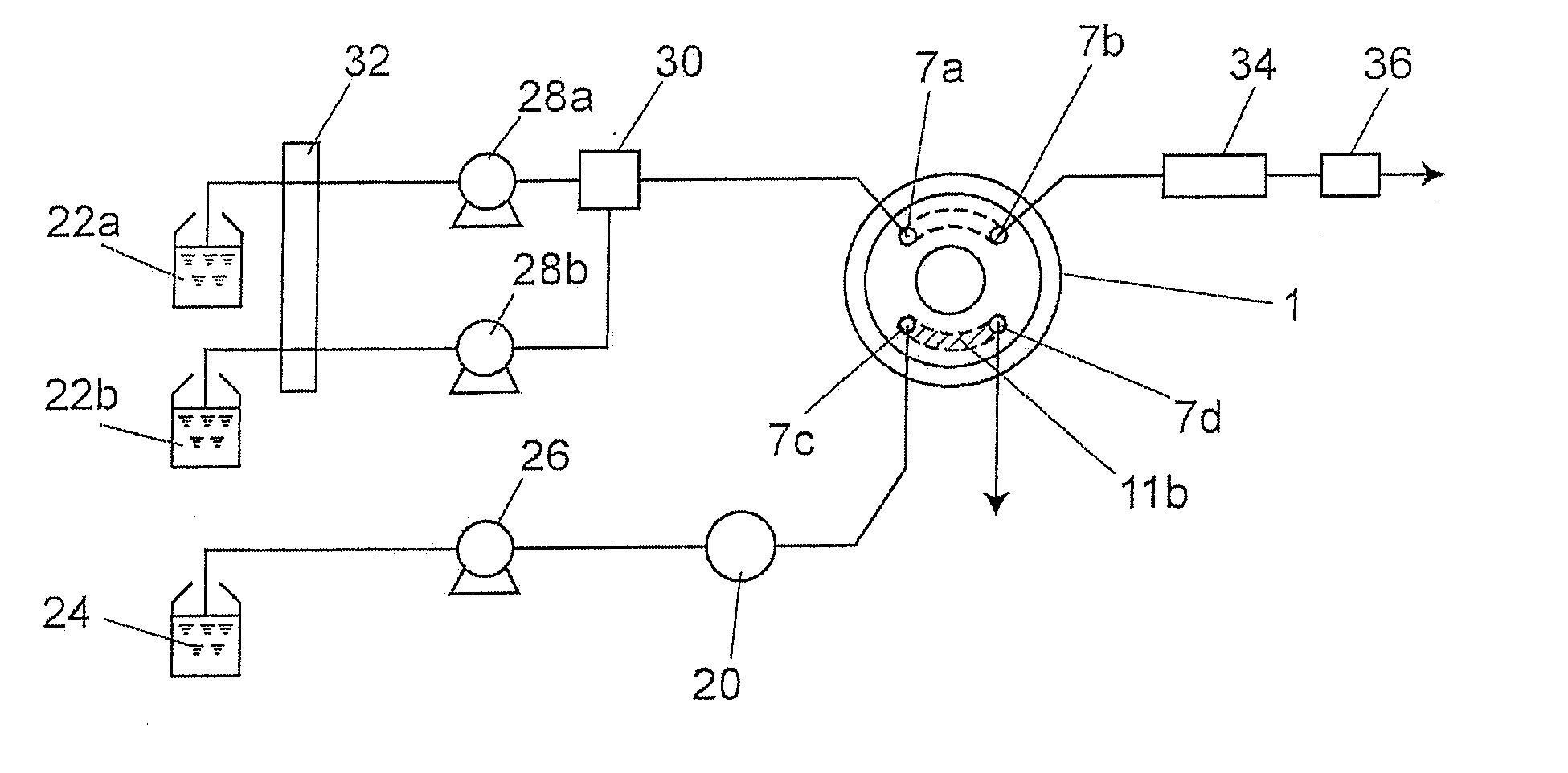
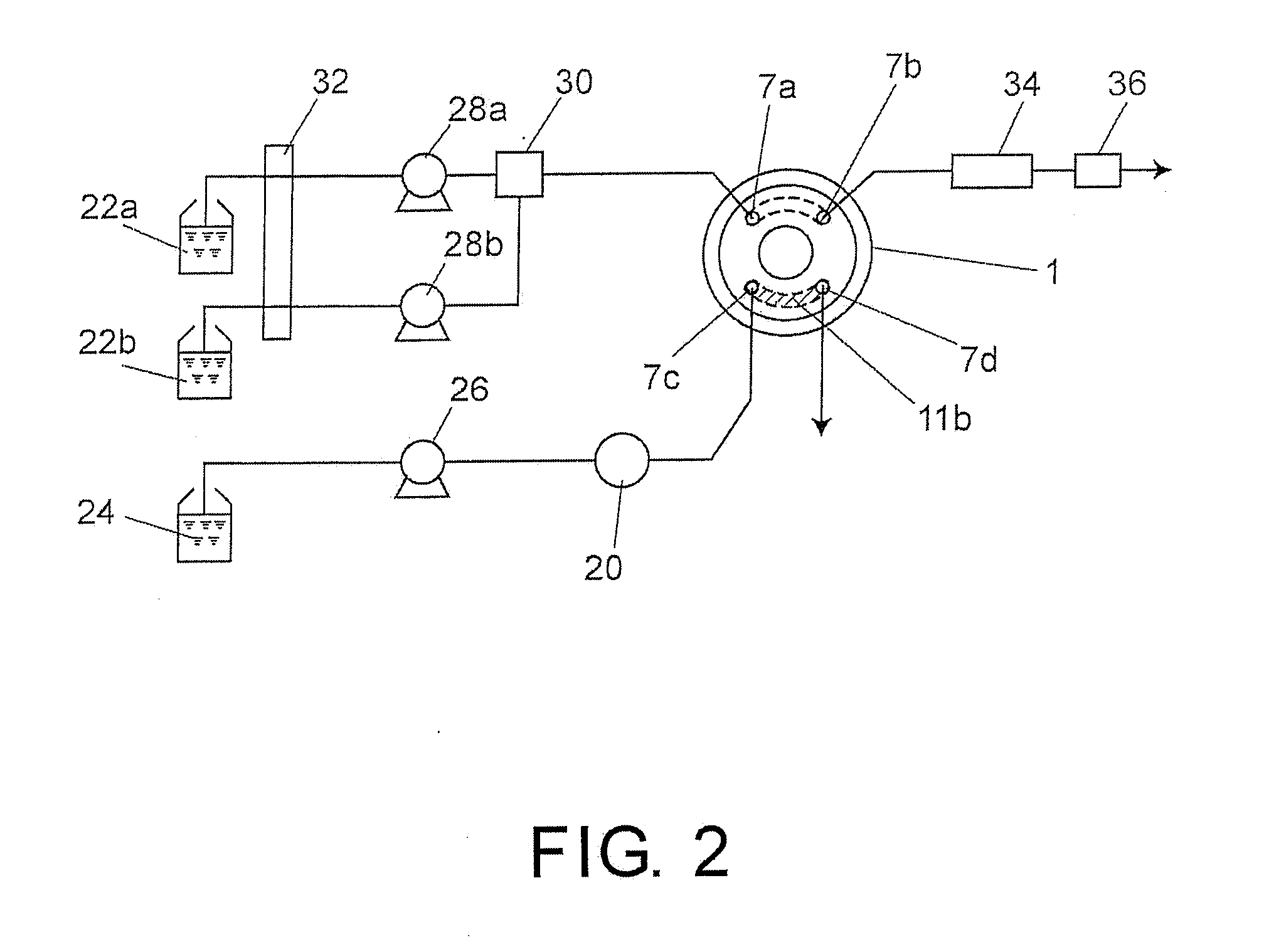
[0033] In the housing top 9, four ports 7a-7d are disposed for being connected to external flow paths, wherein two of them used for the mobile phase for analyzing are an inlet port 7a and an outlet port 7b, and the other two used for the mobile phase for condensing are an inlet port 7c and an outlet port 7d.

[0034] On the surface opposite to t...


PUM

PropertyMeasurementUnit
inner diameteraaaaaaaaaa

Abstract

The present invention is directed to reduce the dead volume in a flow path with trap functions. A flow path switching valve 1 is provided, which includes a rotor, i.e., rotor 3, and a housing top 9 having four ports 7a-7d connected to external flow paths, wherein two ports used for a mobile phase for analyzing are an inlet port 7a and an outlet port 7b, and the other two ports used for a mobile phase for condensing are an inlet port 7c and an outlet port 7d. In the rotor 3, two circular arc-shaped rotor trenches 11a, 11b for communicating two ports are formed at positions corresponding to the ports 7a-7d. The rotor trench 11b is filled with an adsorbent.

Description

CROSS-REFERENCE TO RELATED APPLICATION [0001] This application claims the priority benefit of Japanese Patent Application No. JP 2005-315399, filed Oct. 28, 2005. All disclosure of the Japanese application is incorporated herein by reference. BACKGROUND OF THE INVENTION [0002] 1. Field of Invention [0003] The present invention relates to a high performance liquid chromatograph with trap functions like condensing sample components and a flow path switching valve used by the high performance liquid chromatograph with trap functions. [0004] 2. Description of Related Art [0005] Among quality analyzers used for determining the structures of protein or peptide in the life science field, in order to optimize the measurement sensitivity, those involved in the art make great effects to minimize the flow of the high performance liquid chromatograph (HPLC) at the previous stage. [0006] Generally, HPLCs for ordinary analysis operate by transmitting mobile phase at a flow speed of about 1 mL / min...

Claims


Application Information

Patent Timeline
Patent Type & Authority Applications(United States)
IPC IPC(8): G01N30/00
CPCG01N30/20G01N30/34G01N2030/085G01N2030/202G01N2030/207G01N2030/328Y10T137/86863
Inventor IWATA, YOSUKE
Owner SHIMADZU CORP
Why Eureka
Try Eureka