
Low Noise Fuel Injection Pump

a fuel injection pump, low noise technology, applied in the direction of positive displacement liquid engines, instruments, machines/engines, etc., can solve the problems of less than optimal performance of such assemblies, and achieve the effect of increasing the dead volume, and decreasing the dead volum

Inactive Publication Date: 2009-03-12
GM GLOBAL TECH OPERATIONS LLC
View PDF27 Cites 19 Cited by
  • Summary
  • Abstract
  • Description
  • Claims
  • Application Information

AI Technical Summary

Benefits of technology

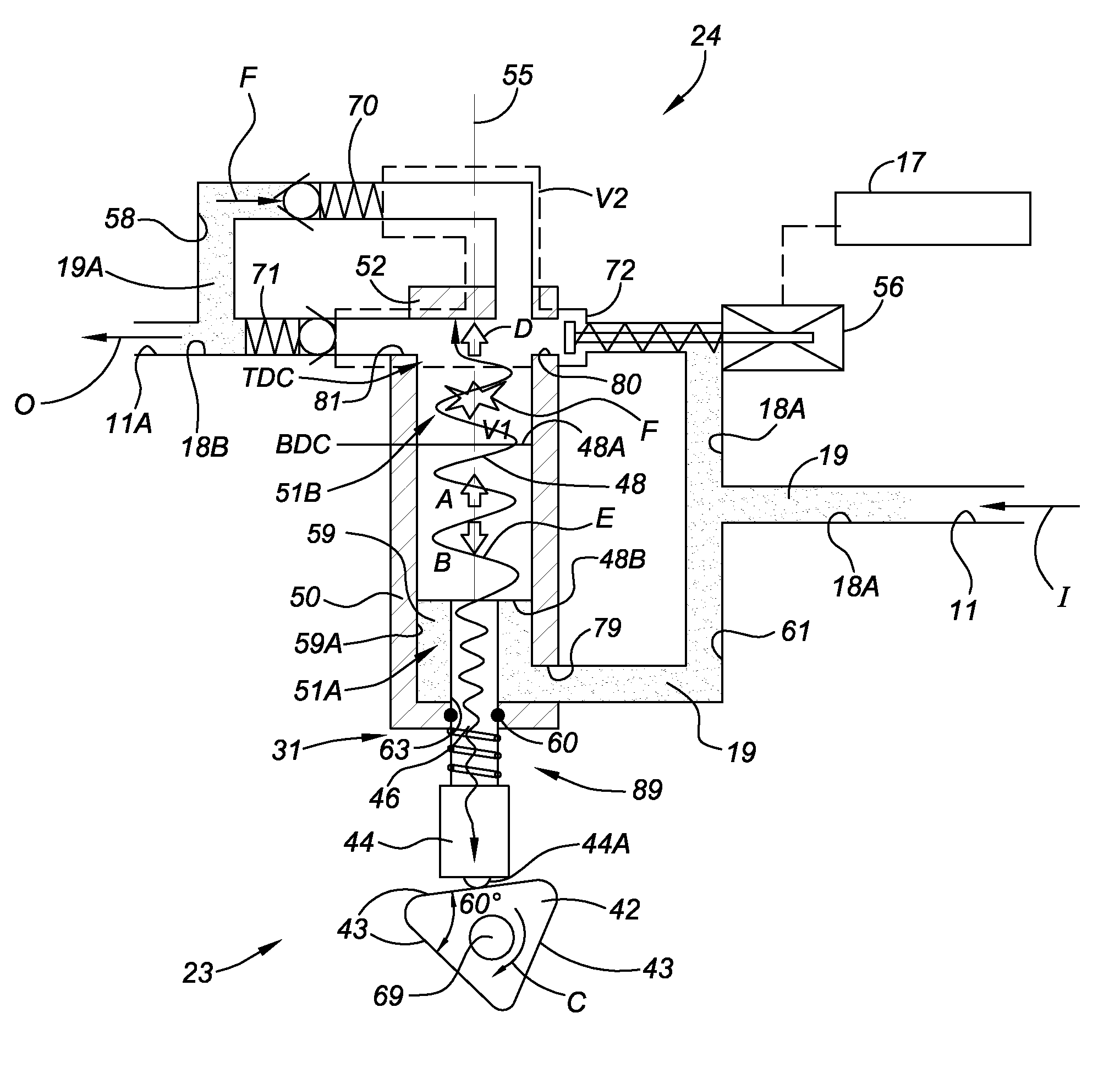
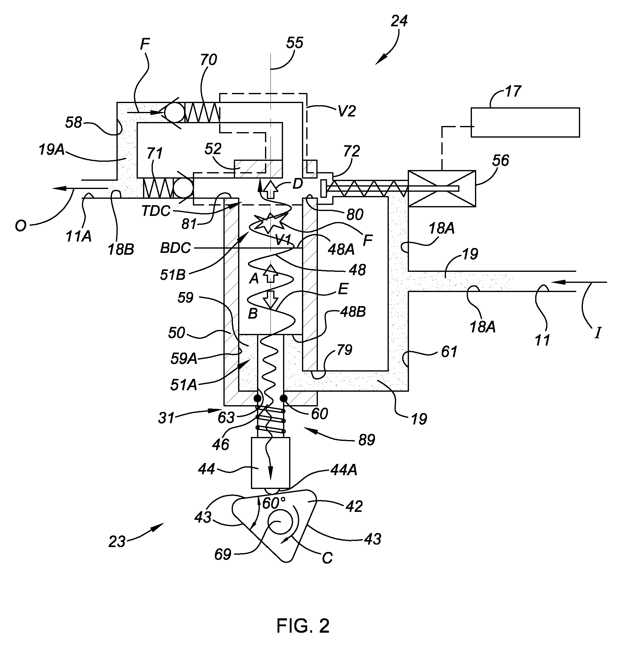
[0009]In another aspect of the invention, at least one of the pump bushing and the plunger includes a cavity for increasing a dead volume within the pump bushing, the cavity being in fluid communication with the pumping chamber via a control orifice.

Problems solved by technology

However, as the higher pressure fuel injection pump systems used with SIDI engines typically employ rail pressures of approximately 150 to 200 bar, the performance of such assemblies may be less than optimal under certain conditions, particularly during periods when the engine is running at a relatively low speed.

Method used


Image

  • Low Noise Fuel Injection Pump
  • Low Noise Fuel Injection Pump
  • Low Noise Fuel Injection Pump

Examples


Embodiment Construction

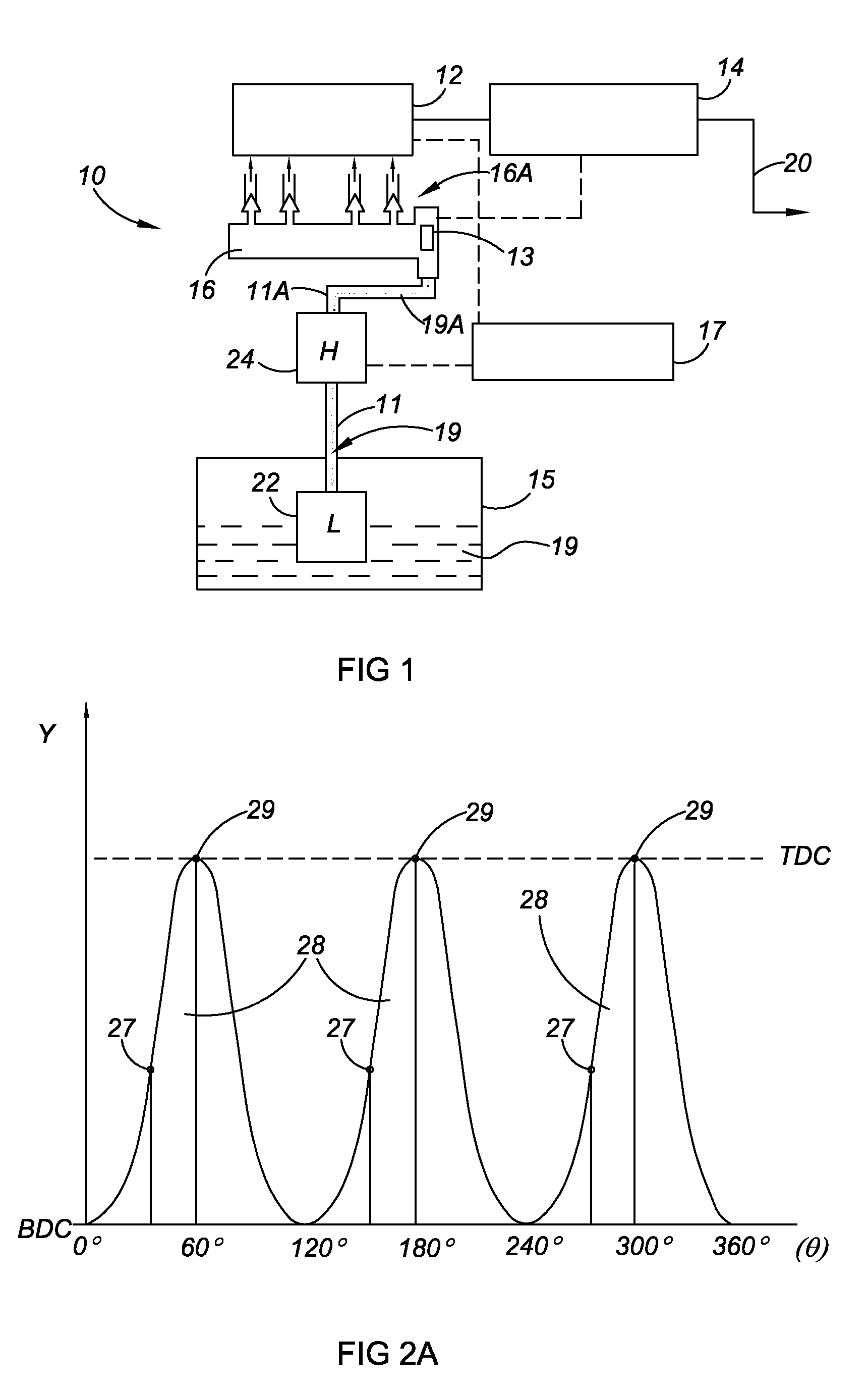
[0029]Referring to the drawings, wherein like reference numbers correspond to like or similar components throughout the several figures, and beginning with FIG. 1, a vehicle 10 has an engine 12 that is operatively connected to a transmission 14. The transmission 14 has an output member 20 in driving connection with a plurality of wheels (not shown) for transferring torque or power from the engine 12 to the wheels (not shown) in order to propel the vehicle 10. In one embodiment, the engine 12 is a Spark Ignition Direct Injection (SIDI) engine, however engine 12 may also be a diesel engine or another style or design of engine utilizing high-pressure fuel injection, the operation of which is known to those skilled in the art.

[0030]The vehicle 10 includes a low pressure fuel reservoir or tank 15 containing a combustible supply of fuel 19, for example gasoline or diesel fuel. A low-pressure supply pump 22, also labeled “L” in FIG. 1 to represent low pressure, is positioned within the tan...


PUM


Abstract

A fuel pump assembly has a bushing defining a pumping chamber, a plunger, a cam follower piece, and a compliance device for absorbing noise by increasing either or both of a hydraulic and / or a mechanical compliance of the fuel pump assembly. The compliance device may includes a spring washer or a press-fit spring. The pump bushing and / or plunger may include a cavity as the compliance device for increasing dead volume, the cavity being in fluid communication with the pumping chamber via an orifice. A deflectable or movable mechanism is positioned within a cavity for increasing dead volume, and a solenoid varies a diameter of the orifice. The moveable mechanism includes a poppet valve having a switching pressure related to engine speed. A vehicle includes an engine, transmission, fuel rail, and a fuel pump assembly configured with at least one compliance device for absorbing a hydraulic noise component.

Description

CLAIM OF PRIORITY[0001]This application claims priority to U.S. Provisional Application No. 60 / 970,573 filed on Sep. 7, 2007, which is hereby incorporated by reference in its entirety.TECHNICAL FIELD[0002]The present invention relates to a direct high-pressure pump assembly having an increased level of hydraulic and / or mechanical compliance for minimizing a hydraulic noise component during a pressurization stroke of the high-pressure pump assembly.BACKGROUND OF THE INVENTION[0003]A fuel pump is used to move an amount of fuel from a fuel source to a fuel delivery system of an internal combustion engine. Depending on the type of fuel delivery system, such as a carburetor, throttle body injection system, port injection system, or direct fuel injection system, the fuel may be delivered at a relatively low- or high-pressure level. For example, a fuel injection system typically requires the fuel to be delivered at a higher pressure than does a carburetor.[0004]Spark Ignition Direct Inject...

Claims


Application Information

Patent Timeline
Patent Type & Authority Applications(United States)
IPC IPC(8): G10K11/00
CPCF02M59/44F02M59/102
Inventor BEARDMORE, JOHN M.TIMMONS, THOMAS V.
Owner GM GLOBAL TECH OPERATIONS LLC
Learn More