Device For Blowing Thermoplastic Containers

a technology of thermoplastic containers and blowing devices, which is applied in the field of manufacturing containers, can solve the problems of high electrical energy consumption of the compressor(s), large dead volume, and large volume of blowing devices of the type under consideration, and achieves the effects of reducing the number of components, reducing the number of dead volumes, and facilitating operation and rapid implementation

Inactive Publication Date: 2008-03-20
SIDEL PARTICIPATIONS SAS
View PDF19 Cites 19 Cited by
  • Summary
  • Abstract
  • Description
  • Claims
  • Application Information

AI Technical Summary

Benefits of technology

[0011] The object of the invention is, therefore, to attempt to satisfy, as far as possible, these continued requirements of users and to propose an improved arrangement of the blowing device which leads to a very substantial reduction in the dead volumes in the circuit for supplying pressurized fluid to the blank arranged in the molding cavity of the mold and which may also lead to lighter and more compact structural assemblies.
[0013] Due to this integrated structure, the outlet of the solenoid valve is moved considerably closer to the end of the nozzle, and as a result the dead volume is considerably reduced in accordance with the principal object sought.
[0014] It will be noted that such an integrated arrangement also offers additional advantages: the elimination of the base for mounting the solenoid valves and possibly the flexible connection, results in a saving in cost (more economical arrangement), a saving in space (possibility of a more compact arrangement and / or space available for mounting other components) and a saving in weight (reduction in the inertia on a rotating structure of the carousel type).
[0016] In a first possible embodiment of the arrangements according to the invention, each housing may be machined so as to form the respective chamber of the mobile core of the solenoid valve; in other words, the respective part of the body is machined, so as not only to form the housing there, but also so that said housing is adapted to receive directly the mobile core of the solenoid valve. This solution offers the advantage of a maximum reduction of the number of component parts and may achieve a substantial saving in the dead volumes; nevertheless, this maximally integrated structure is shown to be impractical for maintenance, as dismantling is lengthy and / or in the case of a serious problem on the chamber of the solenoid valve, the entire corresponding part of the body has to be replaced.
[0017] As a result, a preferred implementation of the arrangements of the invention consists in that each housing is formed to receive a respective solenoid valve cartridge, i.e. a solenoid valve structure comprising a casing defining a chamber accommodating the mobile core. Maintenance is therefore carried out by simply replacing the cartridge, such an operation being easy and rapid to implement.

Problems solved by technology

A blowing device of the type under consideration consumes a very large amount of pressurized fluid, whether at moderate or high pressure.
The constant production of pressurized fluid (air) in large quantities leads to a very high consumption of electrical energy for the functioning of the compressor(s).
In this design, the dead volume was very large, in particular due to the presence of the flexible tube for remote connection.
Nevertheless, in this design which currently continues to exist, the juxtaposition of the two respective bodies of the solenoid valve block and of the nozzle further necessitates fluid passages of a sizeable length, which results in a dead volume which is still too large in terms of consumption.

Method used


Image

  • Device For Blowing Thermoplastic Containers
  • Device For Blowing Thermoplastic Containers
  • Device For Blowing Thermoplastic Containers

Examples


Embodiment Construction

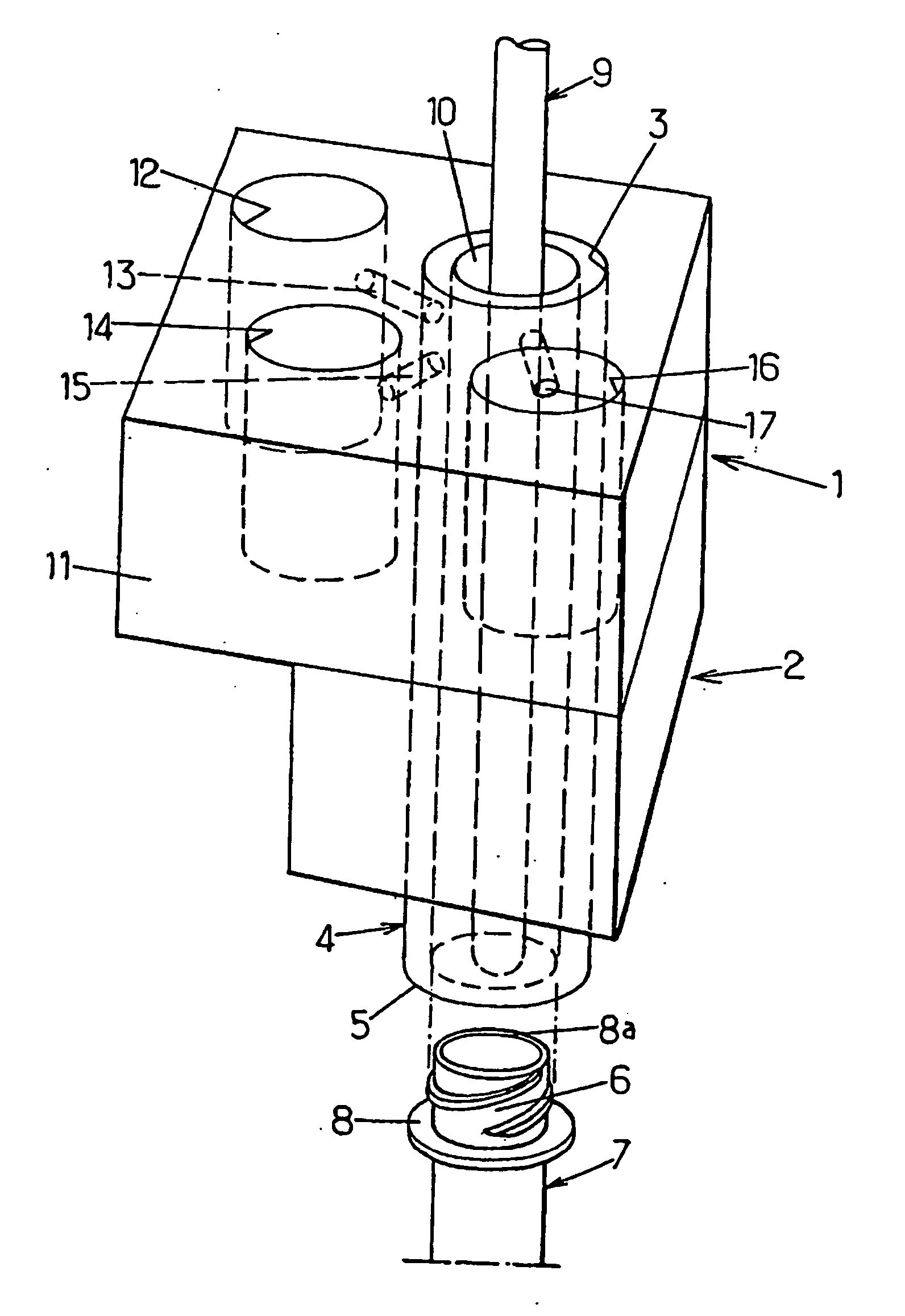
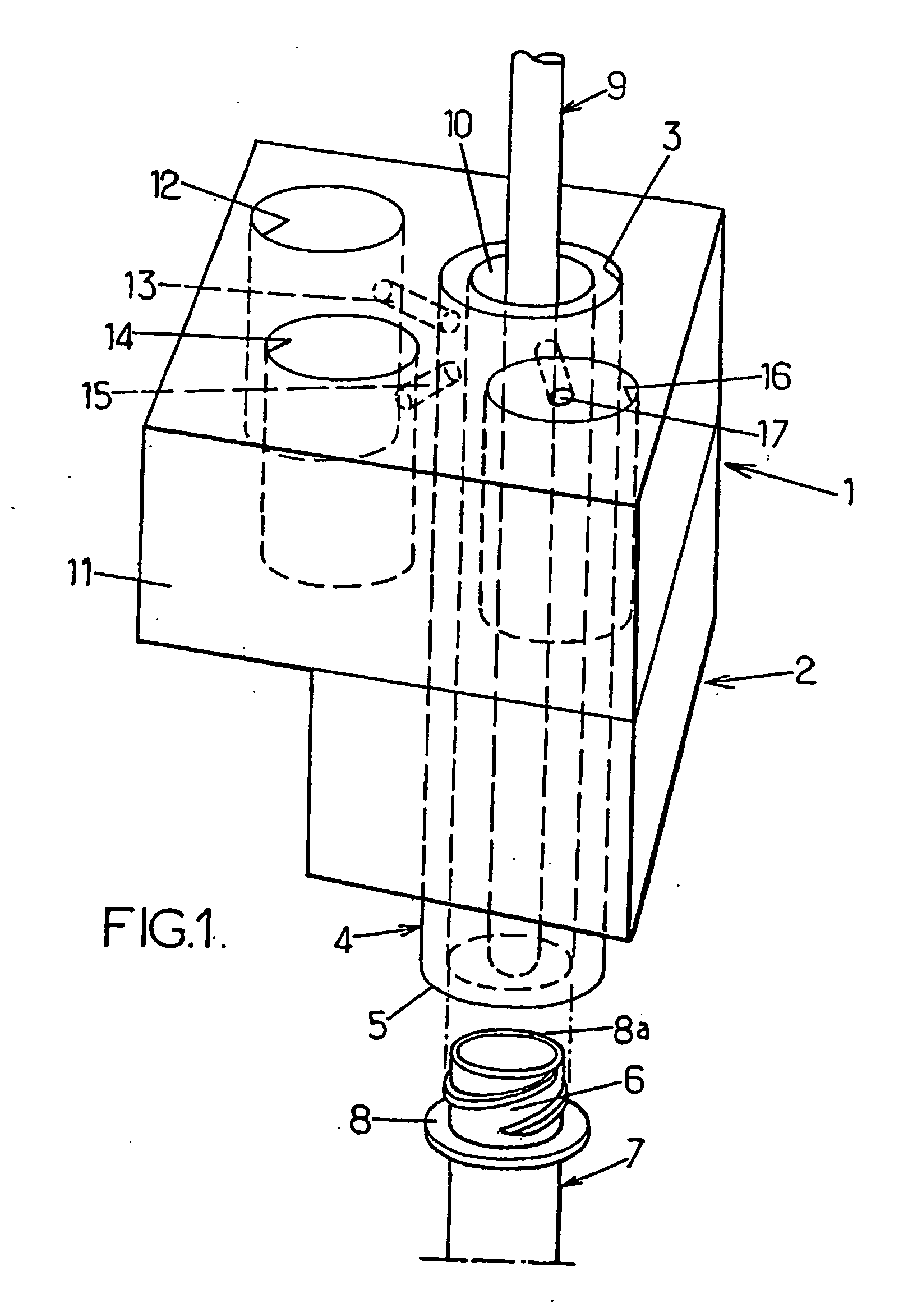
[0030]FIG. 1, to which reference will be made firstly, shows in a very schematic manner a simplified structure of a blowing device implementing the principal arrangements of the invention applied to a device provided with three solenoid valves (respectively pre-blowing, blowing, exhaust). The blowing device, denoted in its entirety by the reference numeral 1, comprises a body 2 having an axial bore 3 in which may be displaced, under the action of generally pneumatic control means (not shown), a mobile element or mobile nozzle 4 in the form of a tubular rod of which one part (not shown) may be designed in the shape of a piston. For clarification, the mutual arrangement of the body 2 and of the mobile nozzle 4 may, for example, be of the type shown in FIG. 1 of the document FR 2 764 544. At its lower end 5, the mobile nozzle 4 is formed in any desired manner to be able to be functionally and sealingly connected to the neck 6 or mouth of a blank 7 of a container (shown here in the form...


PUM

PropertyMeasurementUnit
pressureaaaaaaaaaa
pressureaaaaaaaaaa
dead volumeaaaaaaaaaa

Abstract

A device for blowing, with the aid of a pressurized fluid, containers from thermoplastic blanks closed in a blow mold including a nozzle whose end is functionally and sealingly connected to the neck of the blank and includes several solenoid valves for selectively connecting the nozzle to the source of a moderately pressurized pre-blowing fluid, to the source of a highly-pressurized blowing fluid and to an exhaust for discharging the pre-blowing / blowing fluid, respectively. The inventive device also includes a body which is mechanically associated with the nozzle, incorporates at least one reception area for receiving a solenoid valve and is selectively connectable to the nozzle.

Description

FIELD OF THE INVENTION [0001] The present invention generally relates to the field of manufacturing containers made from thermoplastic material, such as PET or PEN, by a blowing or stretch-blowing method from a blank (preform or intermediate container) and it relates more specifically to improvements made to devices for blowing, by means of a pressurized fluid, containers from thermoplastic blanks, of which the body is enclosed in a blowing mold, said devices comprising a nozzle consisting of an end formed to be functionally and sealingly connected to the neck of a blank and comprising a plurality of solenoid valves for selectively connecting said nozzle to, for example, respectively a source of fluid at moderate pressure for pre-blowing, a source of fluid at high pressure for blowing and an exhaust for discharging the pre-blowing / blowing fluid. BACKGROUND OF THE INVENTION [0002] As known, the nozzle is designed to be axially mobile, in its entirety or partially, above the blowing m...

Claims


Application Information

Patent Timeline
Patent Type & Authority Applications(United States)
IPC IPC(8): B29C49/58B29C49/06B29C49/12B29C49/42
CPCB29C49/06B29C49/12B29C49/42B29C49/4289B29C2049/5827B29K2067/00B29C49/58Y02P70/10B29C49/42855B29C2949/0715B29C2049/6271B29C2049/7831B29C2049/7832
Inventor LEMAISTRE, ERIC
Owner SIDEL PARTICIPATIONS SAS
Why Eureka
Try Eureka