Watch winder cabinet and watch winder apparatus

a technology for watch winders and watch winders, which is applied in the direction of electric winding, instruments, horology, etc., can solve the problems of not providing access into the support chamber, and the fact that the watch winder supports even exist will not be readily apparent to uninformed persons, so as to prevent unauthorized access

Inactive Publication Date: 2005-12-01
AGNOFF CHARLES
View PDF1 Cites 38 Cited by
  • Summary
  • Abstract
  • Description
  • Claims
  • Application Information

AI Technical Summary

Benefits of technology

[0016] A drive means is positioned within the cabinet, e.g., in the lower part of the support chamber, and is attached to the lower part of the support. The drive means is adapted to move the support between raised and lowered positions. In the raised position, the support extends upwardly through an opening in the cabinet top to expose the watch winders carried on the support panel. In the lowered position, the support is completely enclosed within the cabinet chamber with the upper surface...

Problems solved by technology

Opening the door or doors provides access into the storage area, but does not provide access into the support chamber.
In addition, the fact that the watch winder support even exists...

Method used


Image

  • Watch winder cabinet and watch winder apparatus
  • Watch winder cabinet and watch winder apparatus
  • Watch winder cabinet and watch winder apparatus

Examples


Embodiment Construction

[0026] In the following description, terms such as horizontal, upright, vertical, above, below, beneath, and the like, are used solely for the purpose of clarity in illustrating the invention, and should not be taken as words of limitation. The drawings are for the purpose of illustrating the invention and are not intended to be to scale.

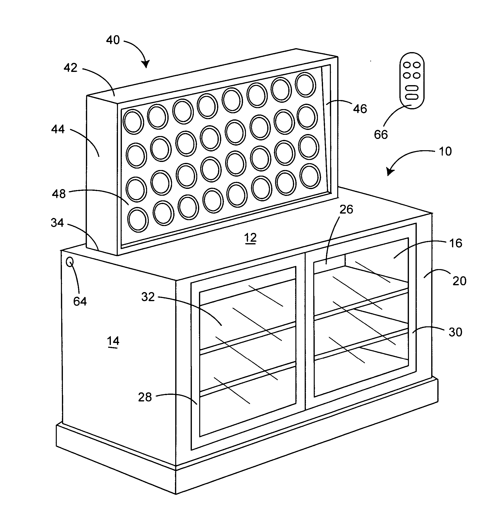
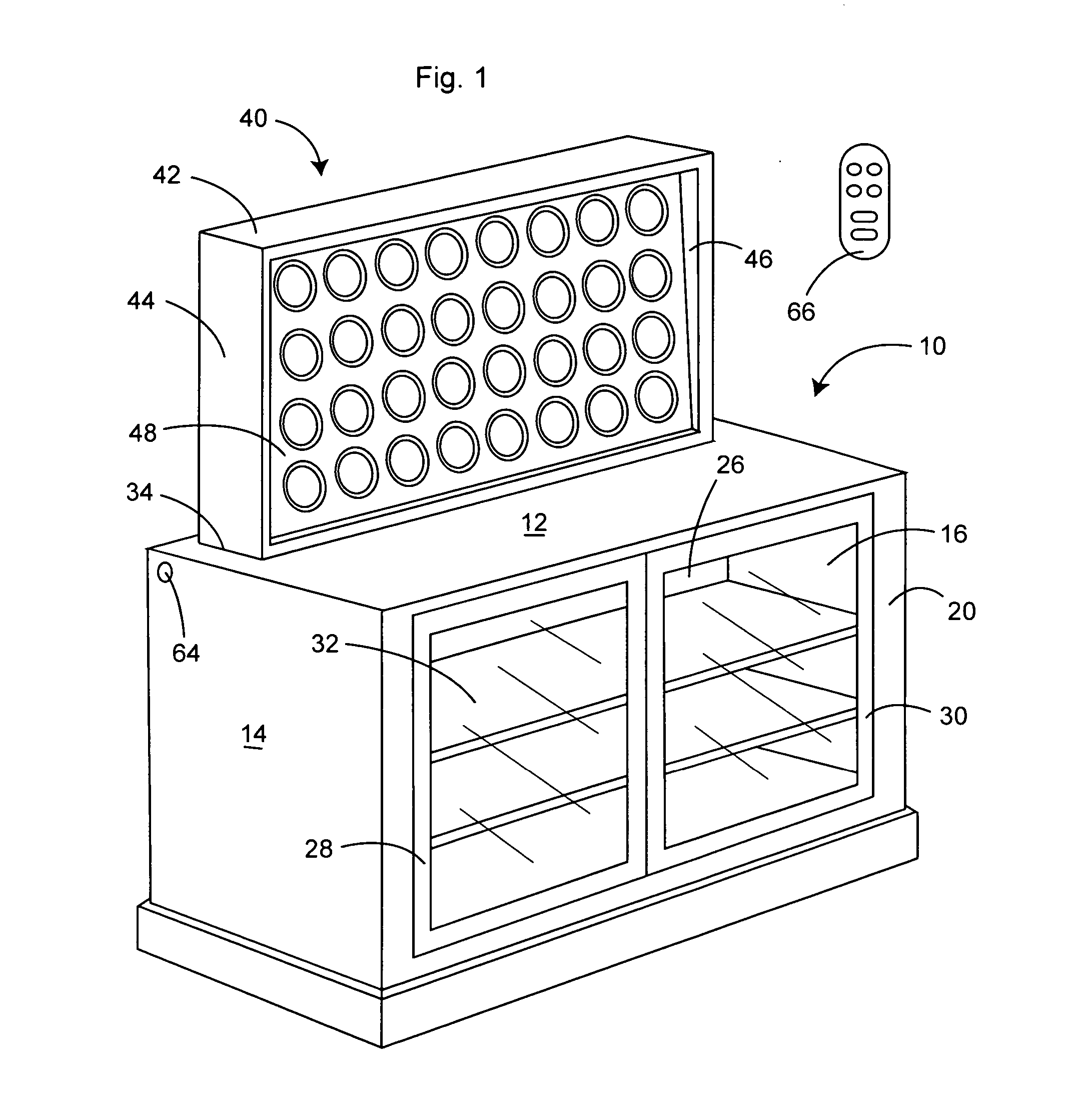
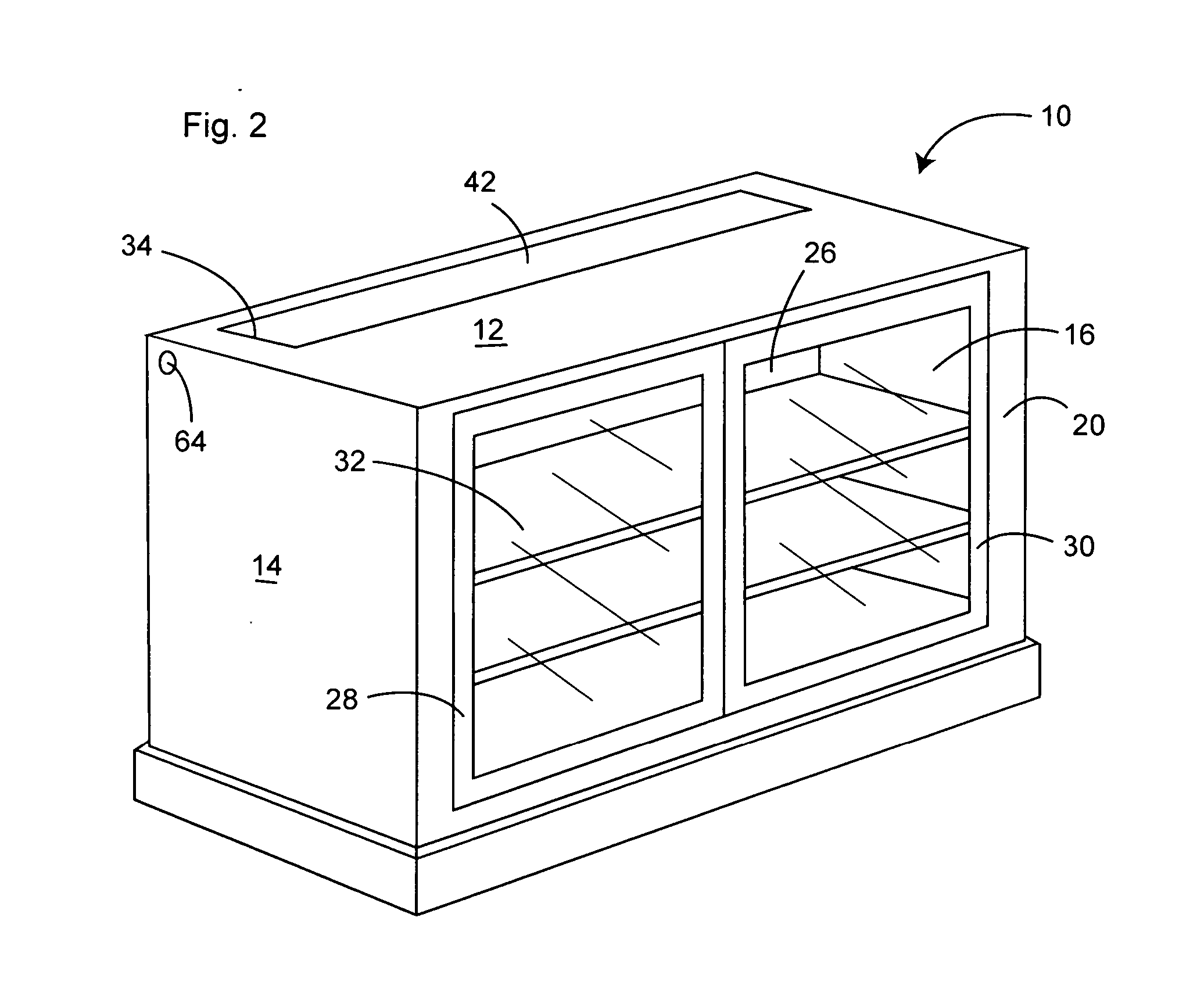
[0027] As best illustrated in FIGS. 1 and 2, cabinet, generally 10, is comprised of a top wall 12 with a horizontal upper surface, opposed parallel side walls 14 and 16, a rear wall 18, and a front wall 20. These walls together define a cabinet interior that is separated into a rear chamber 22 and a front section 24 by divider wall26 mounted parallel to and spaced between rear wall 18 and front wall 20. Front wall 20 includes transparent, e.g., glass paneled, access doors 28 and 30. One or more shelves 32 are mounted within front section 24 between divider wall 26 and front wall 20. Top wall 12 includes opening 34. Divider wall 26 preferably has a ...


PUM


Abstract

A cabinet supporting a plurality of watch winders includes an enclosure having a horizontal top wall with an opening, a rear wall, a front wall, a divider wall separating the enclosure into a rear support chamber and a front storage area. A watch winder support having a top wall and a generally upright watch winder panel having a raised position projecting above the enclosure through the top wall opening from the chamber, and a lowered position within the chamber with the upper surfaces of the enclosure and support top walls being in a plane, thereby preventing access to the watch winders and hiding the watch winders and any supported watches from view. A drive mechanism with a reversible electric motor is used to move the support between its raised and lowered positions.

Description

BACKGROUND OF THE INVENTION [0001] (1) Field of the Invention [0002] The present invention relates generally to a cabinet for storing a plurality of automatic watch winders used to wind self-winding watches, and in particular to a cabinet including a moveable support for a plurality of watch winders and a mechanism for raising the support for access to the watch winders, and lowering the support and watch winders and watches carried on the support into a chamber in the cabinet for secure, inconspicuous storage, while continuing to activate the watch winders as required. [0003] (2) Description of the Prior Art [0004] The winding mechanism of a self-winding watch is comprised of a ball bearing mounted pendulum or rotor that is connected through a gear reduction system to the mainspring of the watch. Generally, the rotor can rotate 360° in either direction. However, there are also so-called “hammer” shaped rotors in older self-winding watches that have a limited travel of 150° to 220° ...

Claims


Application Information

Patent Timeline
IPC IPC(8): A47B51/00G04B3/00G04B5/00G04C1/00G04D7/00
CPCA47B51/00G04D7/009G04B3/006A47B2220/0013
Inventor AGNOFF, CHARLES
Owner AGNOFF CHARLES
Why Eureka
Try Eureka