

Surgical thread
- Summary
- Abstract
- Description
- Claims
- Application Information
AI Technical Summary
Problems solved by technology
Method used
Image

Examples
Embodiment Construction
[0034] The drawings illustrate surgical threads and methods of performing operations with the surgical thread which produce an improved soft tissue lift capable of sustaining a longer lift than that achievable with known surgical threads and face lift procedures.
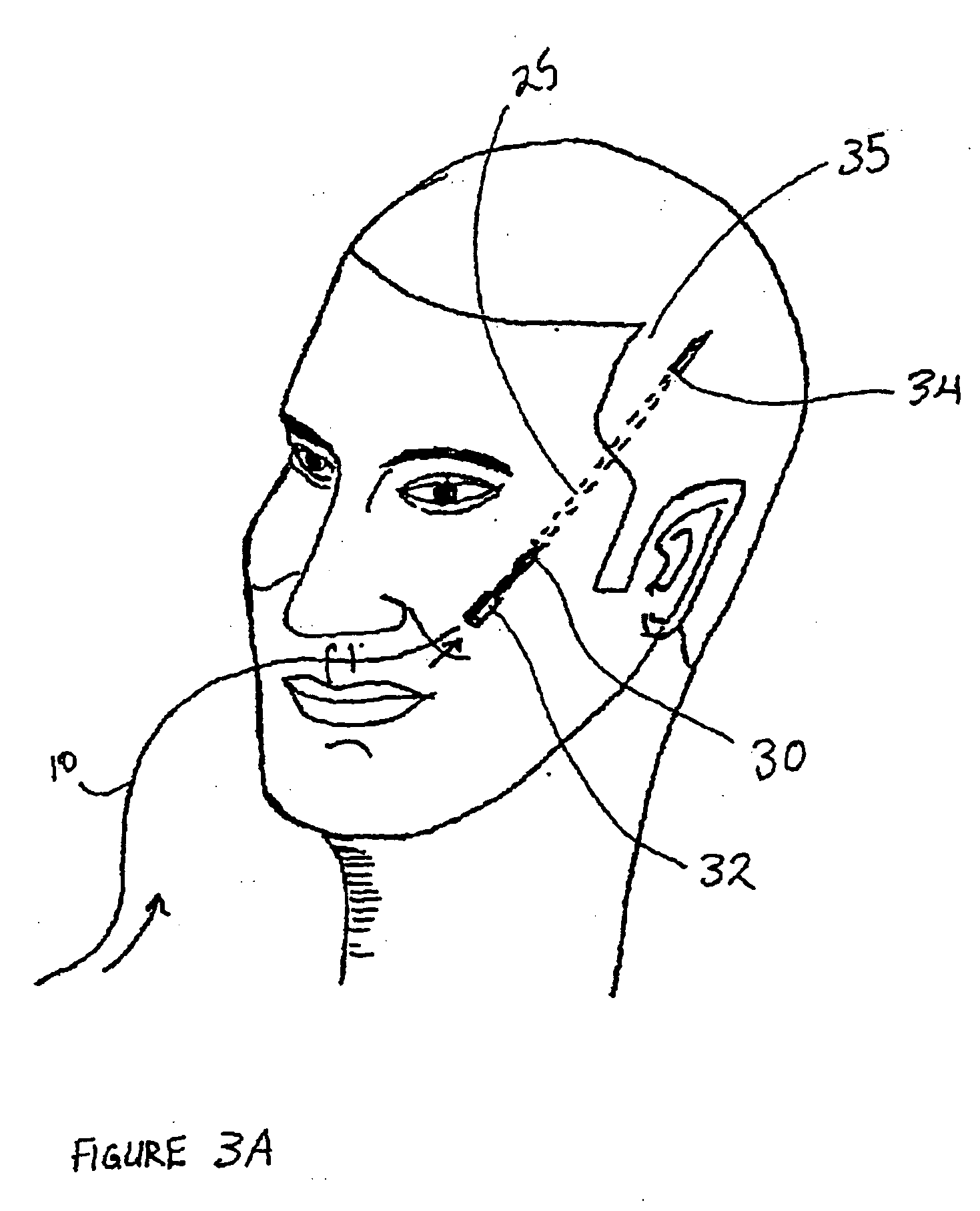
[0035] In the following description specific examples are made to surgical lifting operations on a person's face. However, it is to be understood that the procedure finds equal applicability, and is likely to be used in, other procedures including breast lifting, buttock lifting and the lifting of any other part of the human body that may be desired to be lifted.
[0036] While the description herein refers specifically to surgical procedures performed on humans, it is conceivable that the procedure could be performed on non-humans, and specifically in veterinary medicine on animals.
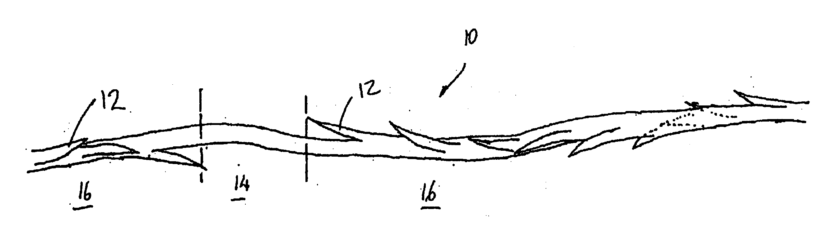
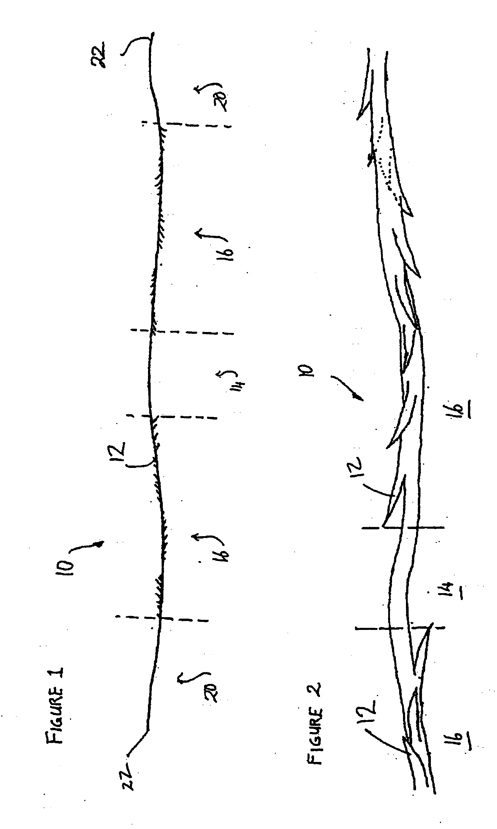
[0037]FIG. 1 illustrates a length of surgical thread 10 for use in surgical procedures, and in particular plastic and cosmetic surgery. The thre...
PUM
 Abstract
Description
Claims
Application Information