Neural interface system with embedded id

a neural interface and embedded id technology, applied in the field of neural interface systems, can solve problems such as major problems such as the inability to identify and obtain stable electrical signals of adequate amplitude, and the degradation of the system performan

Active Publication Date: 2005-12-01
BRAINSGATE LTD
View PDF99 Cites 55 Cited by
  • Summary
  • Abstract
  • Description
  • Claims
  • Application Information

AI Technical Summary

Benefits of technology

[0007] According to a first aspect of the invention, a neural interface system is disclosed. The neural interface system collects multicellular signals emanating from the central nervous system of a patient and transmits processed signals to a controlled device. The system comprises a sensor for detecting multicellular signals. The sensor may comprise a plurality of electrodes. The electrodes are designed to allow chronic detection of multicellular signals. A processing unit is designed to receive the multicellular signals from the sensor and process the multicellular signals to produce processed signals. The processed signals are transmitted from the processing unit to a controlled device. The system comprises two or more discrete components and a first discrete component transmits data or other electronic information to a second discrete component. A unique electronic identifier is embedded in one or more transmissions of the electronic information.

Problems solved by technology

Early attempts to utilize signals directly from neurons to control an external prosthesis encountered a number of technical difficulties.
The ability to identify and obtain stable electrical signals of adequate amplitude was a major issue.
Another problem that has been encountered is caused by the changes that occur to the neural signals that occur over time, resulting in a degradation of system performance.
Neural interface systems that utilize other neural information, such as electrocorticogram (ECOG) signals, local field potentials (LFPs) and electroencephalogram (EEG) signals have similar issues to those associated with individual neuron signals.
Since all of these signals result from the activation of large groups of neurons, the specificity and resolution of the control signal that can be obtained is limited.
Commercialization of these neural interfaces has been extremely limited, with the majority of advances made by universities in a preclinical research setting.

Method used


Image

  • Neural interface system with embedded id
  • Neural interface system with embedded id
  • Neural interface system with embedded id

Examples


Embodiment Construction

[0030] Reference will now be made in detail to the present embodiments of the invention, examples of which are illustrated in the accompanying drawings. Wherever possible, the same reference numbers will be used throughout the drawings to refer to the same or like parts.

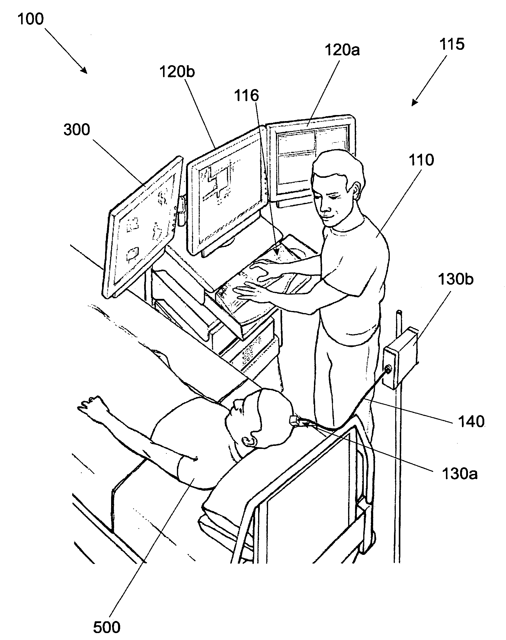
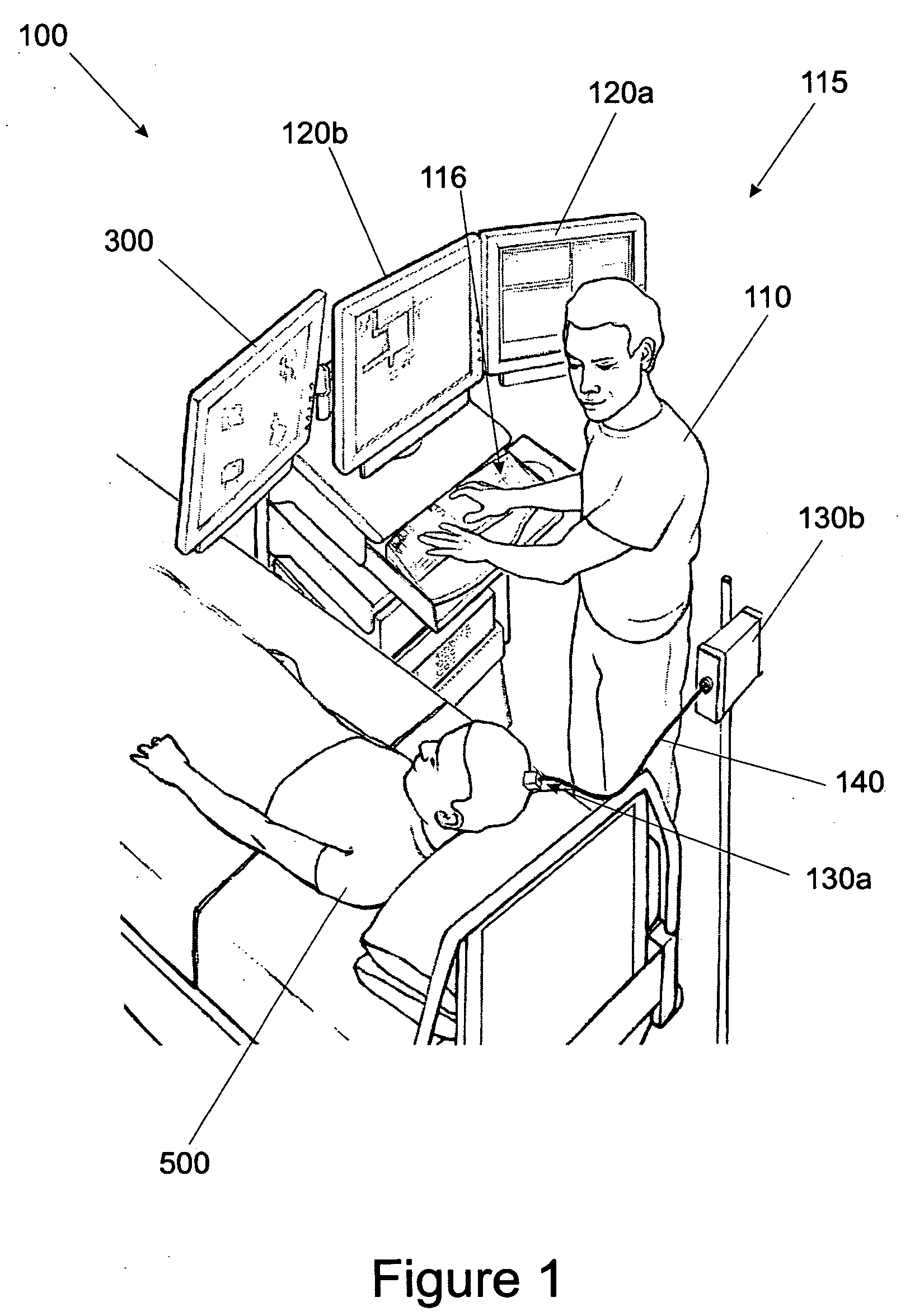
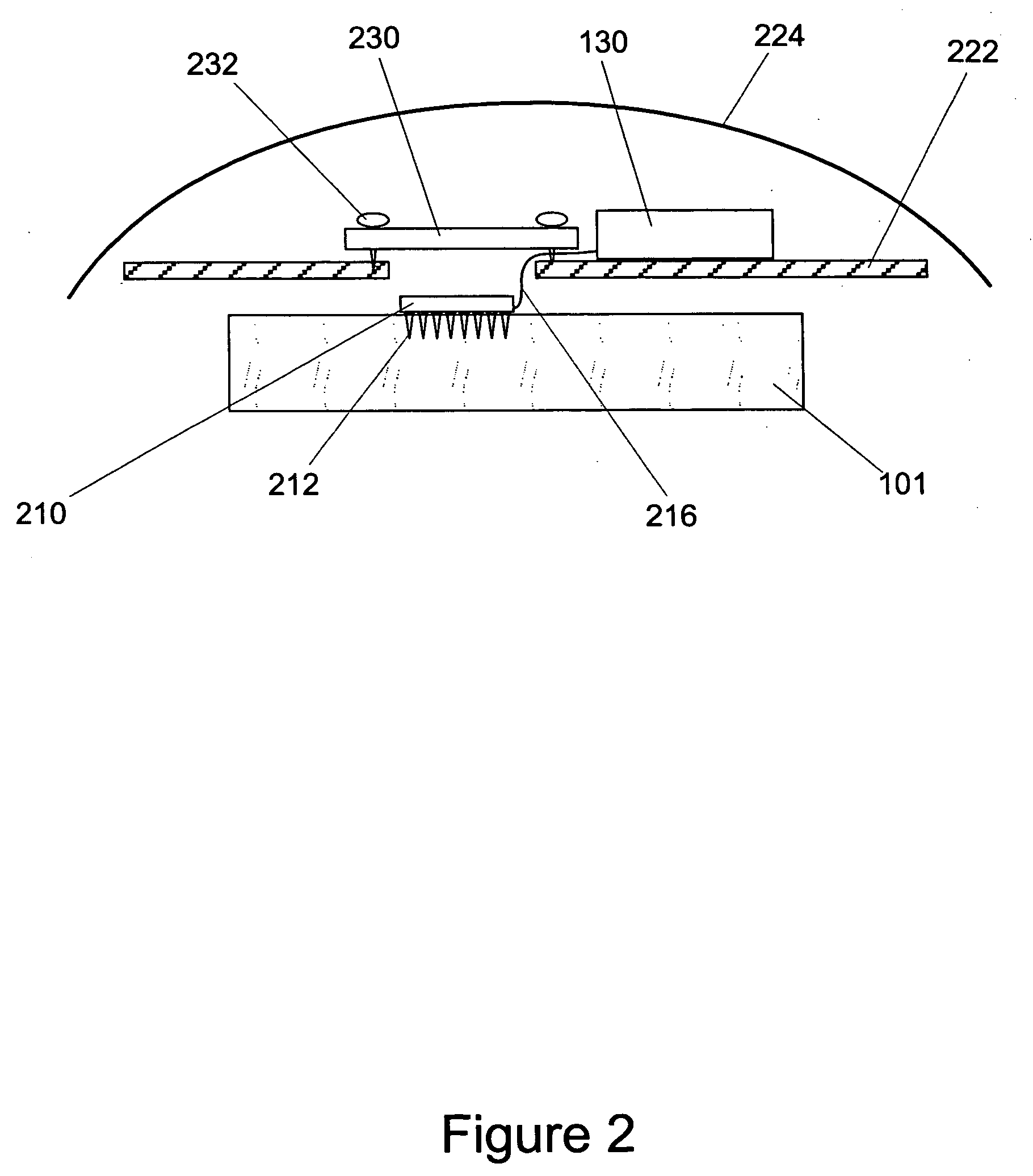
[0031] Systems and methods consistent with the invention detect neural signals generated within a patient's body and implement various signal processing techniques to generate processed signals for transmission to a device to be controlled. In one exemplary embodiment, a neural interface system includes multiple discrete components which can each transmit electronic information to a separate component through the use of a physical cable, including one or more of electrically conductive wires or optical fibers. Alternatively or additionally, transmission of data or other electronic information between discrete components can be accomplished wirelessly, by one or more discrete components including a transceiver that m...


PUM


Abstract

A system and method for a neural interface system with a unique identification code includes a sensor including a plurality of electrodes to detect multicellular signals, an processing unit to process the signals from the sensor into a suitable control signal for a controllable device such as a computer or prosthetic limb. The unique identification code is embedded in one or more discrete components of the system. Internal and external system checks for compatibility and methods of ensuring safe and effective performance of a system with detachable components are also disclosed.

Description

[0001] This application claims the benefit of priority under 35 U.S.C. § 119(e) of U.S. provisional application No. 60 / 524,969, filed Nov. 25, 2003.FIELD OF THE INVENTION [0002] The present invention relates to neural interface systems with unique embedded identifiers, and, more particularly, to systems and methods whereby a neural interface system utilizes the unique embedded electronic signature or identifier to assure compatibility of a multiple component system. DESCRIPTION OF RELATED ART [0003] Neural interface devices are currently under development for numerous applications including restoration of lost function due to traumatic injury or neurological disease. Sensors, such as electrode arrays, implanted in the higher brain regions that control voluntary movement can be activated voluntarily to generate electrical signals that can be processed by a neural interface device to create a thought invoked control signal. Such control signals can be used to control numerous devices ...

Claims


Application Information

Patent Timeline
Patent Type & Authority Applications(United States)
IPC IPC(8): A61B5/00A61B5/04
CPCA61B5/0031A61B5/04001A61B2562/08A61B2560/045A61B2560/0223A61B5/24
Inventor FLAHERTY, J. CHRISTOPHERCAPACHIONE, L. RENEEMORRIS, DANIEL S.CAPLAN, ABRAHAM H.SALEH, MARYAMGUILLORY, K. SHANE
Owner BRAINSGATE LTD
Why Eureka
Try Eureka