

Foot prosthesis with resilient multi-axial ankle
a multi-axial, resilient technology, applied in the field of prosthetic feet, can solve the problems of the inability to adapt to the shape of the foot prosthesis,
- Summary
- Abstract
- Description
- Claims
- Application Information
AI Technical Summary
Benefits of technology
Problems solved by technology
Method used
Image

Examples
Embodiment Construction
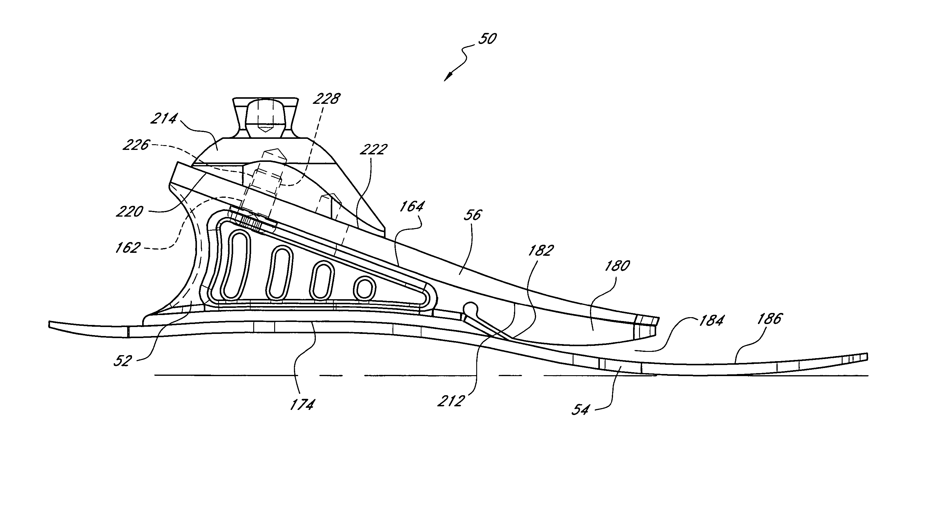
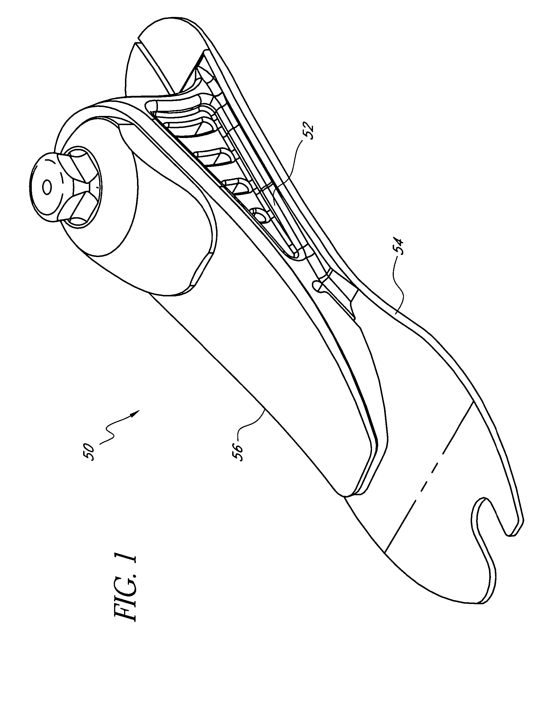
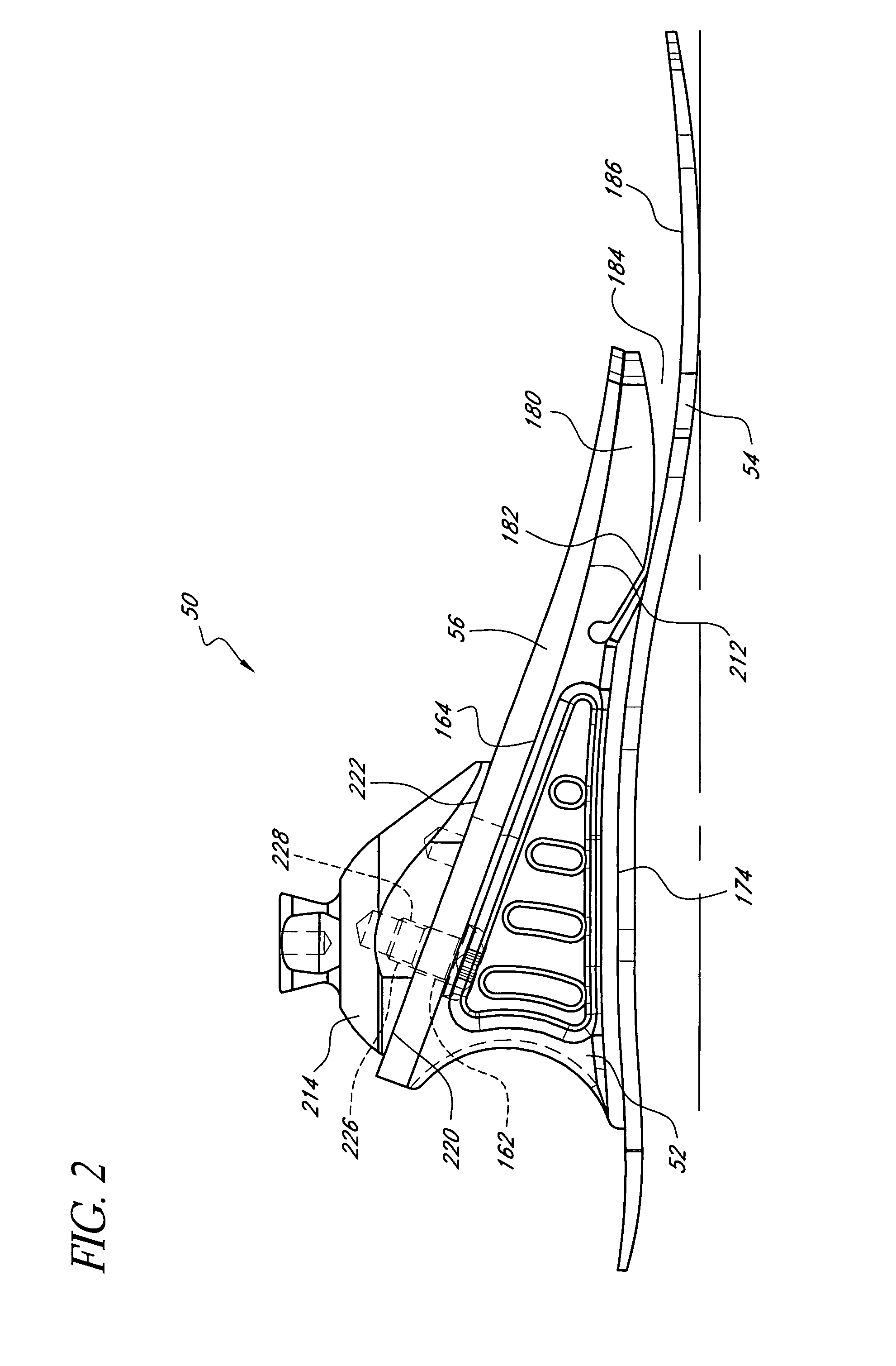
,” one will understand how the features of the preferred embodiments provide advantages, which include soft heel, stabilization at heel strike, progressive stiffness at heel strike and toe off, smooth rollover, guided rollover, progressively increasing support from mid stance through toe off, natural-feeling toe off, variable stiffness during rollover and a reduction in stresses in members that secure various foot components to one another.
[0008] One embodiment of the present foot prosthesis comprises a lower element, an upper element, a resilient ankle member and an attachment adapter operatively connected to an upper surface of the upper element. The ankle member is positioned between the lower and upper elements, and completely separates the lower element from the upper element such that the lower element does not contact the upper element. A gap exists between a lower front edge of the adapter and the upper surface of the upper element.
[0009] Another embodiment of the present f...
PUM
 Abstract
Description
Claims
Application Information