Dynamic graphic user interface

a graphic user interface and dynamic technology, applied in the field of computer system user interfaces, can solve the problems of limited opportunities currently available to reconfigure conventional computer applications, neither visually stimulating nor pleasing to the ey

Inactive Publication Date: 2005-12-08
INTEL CORP
View PDF12 Cites 36 Cited by
  • Summary
  • Abstract
  • Description
  • Claims
  • Application Information

AI Technical Summary

Benefits of technology

[0006] In a preferred embodiment, each element of the user interface in the present invention is surrounded by a dynamic edge instead of being surrounded by a static edge as in conventional systems. The present invention does not limit the shape of the core of the element to be rectangular, but allows the elements to be of any shape and in one or more pieces. The dynamic aspect of the present invention comes from the possibility of sticking or adhering together several cores in a visually coherent unit and doing it in real time.

Problems solved by technology

Therefore, limited opportunities are presently available to reconfigure conventional computer applications.
Such interfaces can be regarded as static because they do not allow the possibility of configuration by end-users.
Moreover, all these elements are often of a rectangular or square shape, which is neither visually stimulating nor very pleasing to the eye.

Method used


Image

  • Dynamic graphic user interface
  • Dynamic graphic user interface
  • Dynamic graphic user interface

Examples


Embodiment Construction

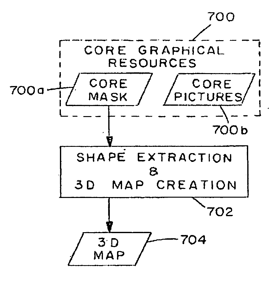
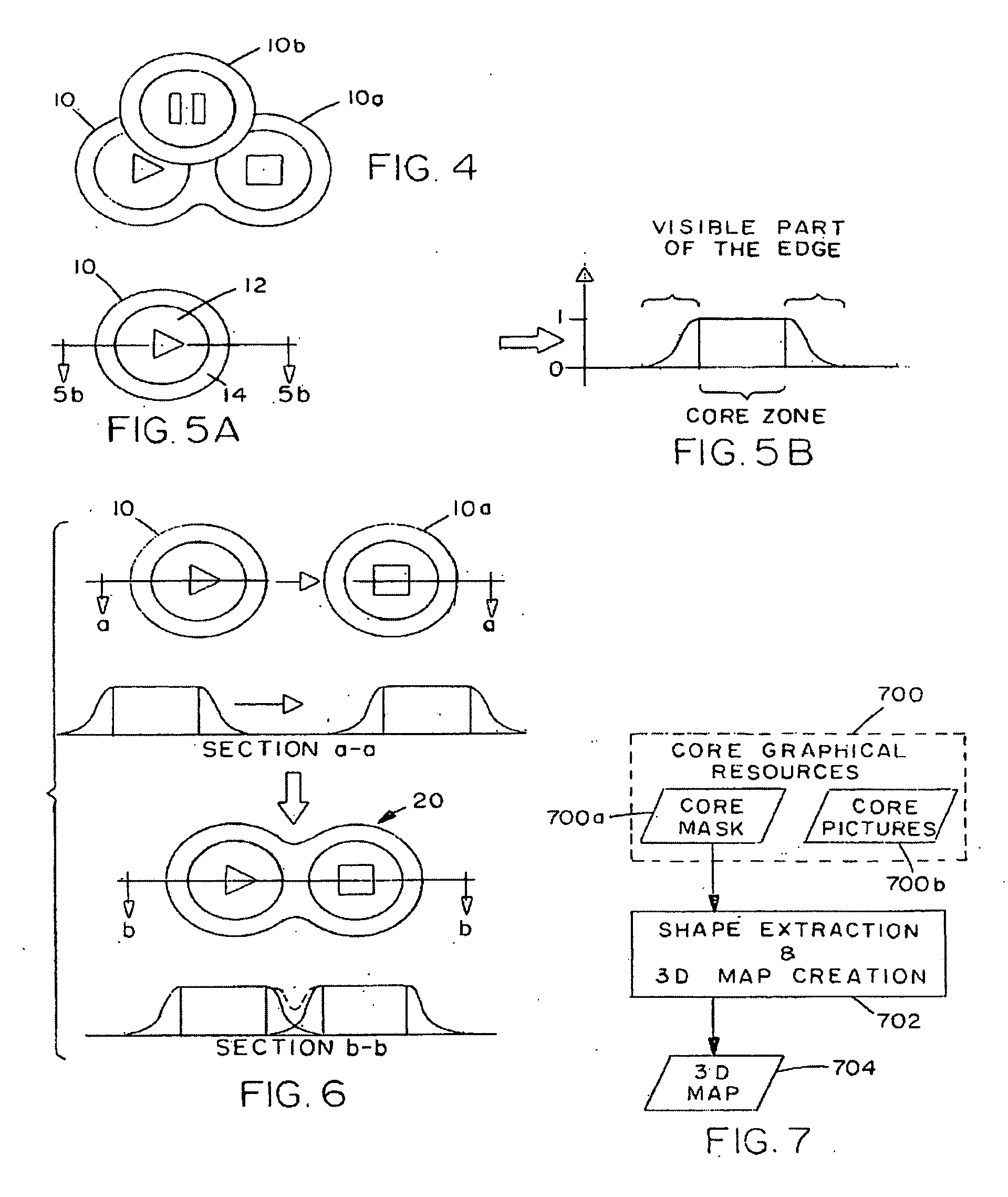
[0021] In the specific embodiments to be described, the invention provides a dynamic graphic user interface in an application program.

[0022] Turning now to FIGS. 5a and 5b, the element 10 is shown with the core 12 and edge or dynamic zone 14 in a preferred embodiment. In FIG. 5b, each point of the element 10 can be assigned a numerical value. This is illustrated with a conventional x-y axis in FIG. 5b, with the y-axis values representing the numerical value assigned to the point, also called a height value. For all the points which are inside the core 12, the height is preferably equal to a value of one as illustrated in FIG. 5b.

[0023] For all points which correspond to the edge 14, the height varies from a value of one, if the point is close to the core 12, and tends towards zero value as one moves away from the core 12 as also shown in FIG. 5b. Persons skilled in the art will recognize that the two-dimensional representation in FIG. 5b applies to other transverse sections throug...


PUM


Abstract

A Graphical User Interface or “GUI” for use with a computer operating systems that operates dynamically according to the user's preferences. Each element of the GUI is surrounded by a dynamic edge which allows the user to combine two or more elements together to create a visually coherent unit in real time. Users can merge or fuse together two or more edges together thus creating a combined group that has aspects and qualities from the constituent elements. Particular colors and color combinations can be created by the user along with user selected shapes and sizes of individual elements selected from a library of element shapes and sizes. The grouped elements can then be separated back to the individual elements for use in different applications or other groupings as later desired by the user.

Description

RELATED APPLICATION DATA [0001] This application claims the benefit of U.S. Provisional Application Ser. No. 60 / 153,993 filed Sep. 15, 1999, the disclosure of which is incorporated herein by reference.BACKGROUND OF THE INVENTION [0002] The invention described and claimed herein relates generally to user interfaces for computer systems and more particularly, graphical user interfaces. A graphical user interface or “GUI” facilitates communications between a computer operating system and a computer user. The computer system includes software and hardware, including hardware for a GUI which typically includes both a visual display (commonly a computer monitor) and selector device (commonly a mouse, trackball or keyboard). Through the visual display, the computer system can deliver graphical and textual output to the user. [0003] A conventional GUI is made up of elements presented on the visual display which allow a user to activate an application in a computer operating system. Examples...

Claims


Application Information

Patent Timeline
Patent Type & Authority Applications(United States)
IPC IPC(8): G06F3/048G06F3/14G09G5/00
CPCG06F3/0481
Inventor JACQUES BROUAUX, ALEXANDRE MARC
Owner INTEL CORP
Why Eureka
Try Eureka