
Insert for a chain link fence

a chain link fence and insert technology, applied in the field can solve the problems of unattractive institution appearance, low privacy of enclosed areas, and low privacy of activities in those areas, and achieve the effects of reducing the number of chain link fences, and reducing the number of people in the area

Inactive Publication Date: 2005-12-15
MOORE TERRY F
View PDF18 Cites 6 Cited by
  • Summary
  • Abstract
  • Description
  • Claims
  • Application Information

AI Technical Summary

Benefits of technology

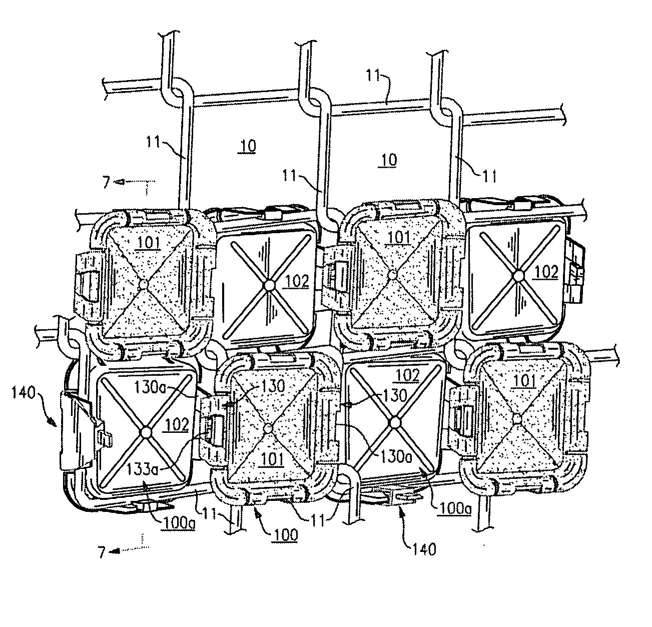
[0005] The present invention is directed to overcoming one or more of the problems or disadvantages associated with the prior devices. As will be more readily understood and fully appreciated from the following detailed descriptions of a preferred embodiment of the present invention, the invention is embodied in an improved insert for a chain link fence wherein a plurality of such inserts, each formed in a shape substantially the same as the square or diamond shaped matrix formed by the wires of the fence crossing over each, are connected to each other entrapping there between the wires from which the fence is formed.

Problems solved by technology

Such enclosed areas, however, create an institutional appearance and are generally unattractive.
In addition, because of the post-supported interwoven wires which produce a matrix of square or diamond shaped openings from the wires crossing over each other, such chain link fences offer little, if any, privacy for the areas enclosed or activities within those areas.

Method used


Image

  • Insert for a chain link fence
  • Insert for a chain link fence
  • Insert for a chain link fence

Examples


Embodiment Construction

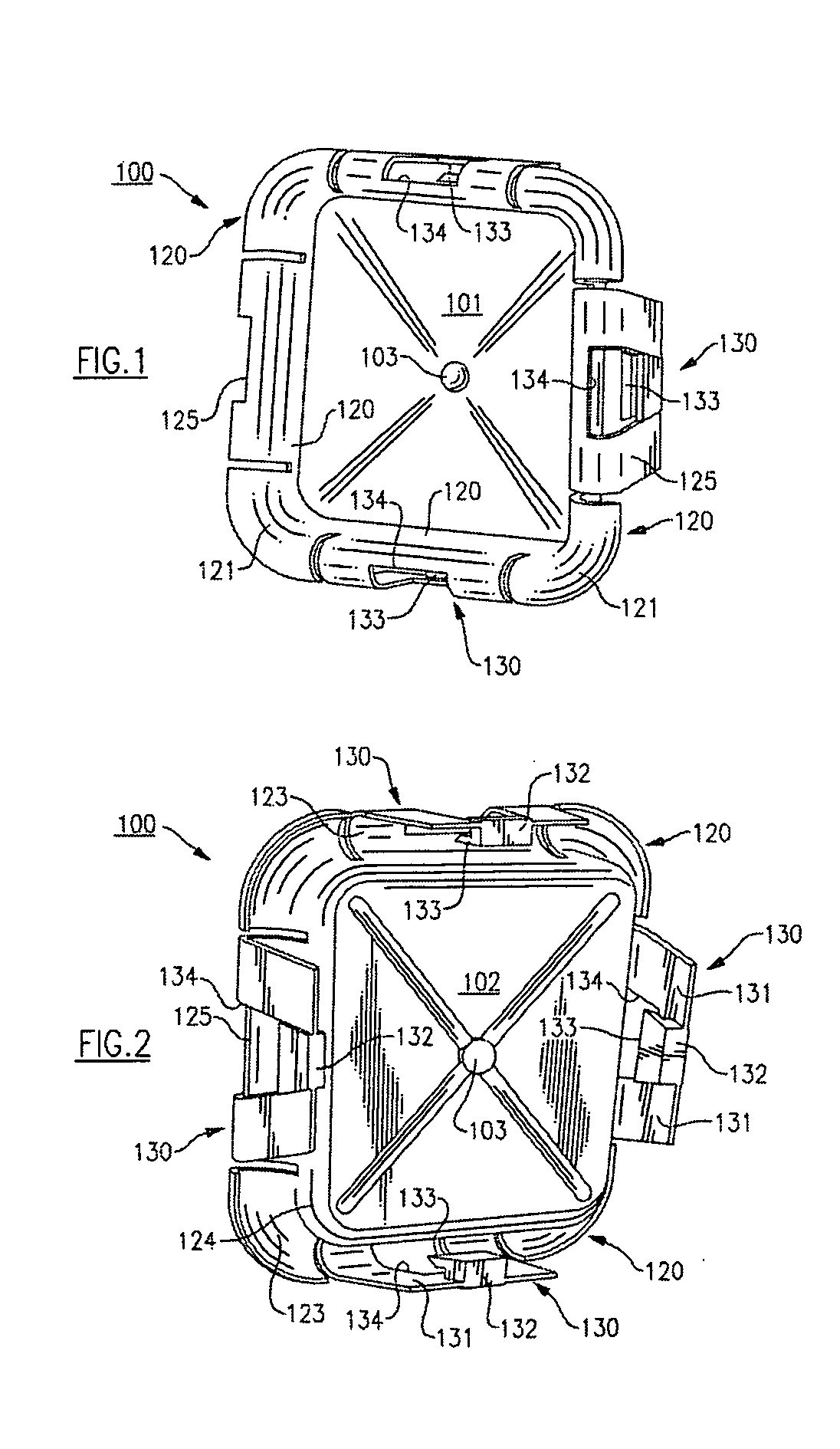
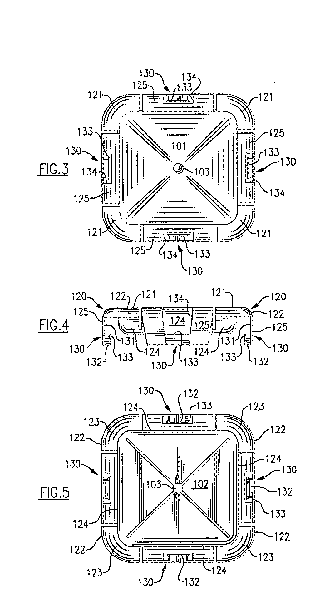
[0018] Referring now to the drawings, there is illustrated in FIGS. 1-5 a preferred embodiment of a chain link fence insert 100 which is preferably molded from plastic and can be fabricated in various colors. By arranging various colored inserts 100 in a pattern, a design or message can be created in the fence matrix, or by arranging the same colored inserts 100 in the fence matrix a uniformly colored fence can be formed. As illustrated in these drawings, the insert 100 is formed in a substantially square or diamond shape to conform to the matrix openings 10 (illustrated in FIG. 6) of a chain link fence. The insert 100 has one face 101 (referred to for convenience of illustration as a “front” face) and an opposed face 102 (referred to for convenience of illustration as a “rear” face). These references, however, are only used for convenience of illustration, and assist in the description of the positioning of one insert relative to an adjoining insert on a chain link fence into which...


PUM


Abstract

An improved insert for a chain link fence wherein a plurality of such inserts, each formed in a shape substantially the same as the square or diamond shaped matrix formed by the wires of the fence crossing over each, are connected to each other entrapping there between the wires from which the fence is formed.

Description

FIELD OF THE INVENTION [0001] This invention relates generally to the field of ______, and more particularly to ______ BACKGROUND OF THE INVENTION [0002] This invention relates in general to an insert for a chain link fence and, in particular, to an improved chain link fence insert which can function to improve privacy and provide a decorative effect using the interwoven wires of the chain link fence which form a wire matrix. [0003] Chain link fences are frequently used for enclosing residential, commercial, agricultural and / or governmental areas to provide a defined enclosure. Such enclosed areas, however, create an institutional appearance and are generally unattractive. In addition, because of the post-supported interwoven wires which produce a matrix of square or diamond shaped openings from the wires crossing over each other, such chain link fences offer little, if any, privacy for the areas enclosed or activities within those areas. [0004] While various attempts have been made...

Claims


Application Information

Patent Timeline
Patent Type & Authority Applications(United States)
IPC IPC(8): E04H17/06
CPCE04H17/066
Inventor MOORE, TERRY F.
Owner MOORE TERRY F
Learn More