Enclosure for telecommunications equipment

a technology for telecommunications equipment and enclosures, applied in the field of enclosures for telecommunications equipment, can solve the problems of metal cabinets, not particularly resistant to dents, scratches, and dents, and achieve the effect of reducing the risk of telecommunications equipment damage, and improving the protection of equipmen

Inactive Publication Date: 2005-12-15
CHARLES INDS
View PDF43 Cites 16 Cited by
  • Summary
  • Abstract
  • Description
  • Claims
  • Application Information

AI Technical Summary

Benefits of technology

[0010] A bonding / grounding strap is provided that has first and second ends each of which is attachable to a respective one of the legs of the mounting frame. Each of the first and second ends of the bonding / grounding strap has a keyhole slot for receiving a fastener. The keyhole slots having a first portion that is larger than a head of the fastener such that the head can pass through the first portion and a second portion that is smaller than the head of the fastener such that the head is prevented from passing through the slot.

Problems solved by technology

Unfortunately, these metal cabinets have a number of drawbacks.
For example, they are not particularly resistant to dings, dents and scratches and can become quite beat-up over time or even during the installation process.
This adversely affects not only the appearance of the cabinet, but also makes it more susceptible to corrosion.
Moreover, because these cabinets are constructed of multiple pieces that are bolted together, they can be difficult to seal against the weather.
The doors to the cabinet also can easily be knocked or left open or ajar by careless technicians further compromising the security and integrity of the cabinet.
These issues are of particular concern in areas subject to flooding because floodwater can infiltrate the cabinet and the telecommunications equipment can become submerged.
Another significant issue with these metal cabinets is that access to the interior can be awkward and quite limited.
While this can be alleviated somewhat by providing an extra set of doors on the rear of the cabinet, access to the sides will still be limited and, as noted above, the extra doors increase the potential for ajar, misaligned or otherwise improperly sealed parts that compromise the integrity of the cabinet.

Method used


Image

  • Enclosure for telecommunications equipment
  • Enclosure for telecommunications equipment
  • Enclosure for telecommunications equipment

Examples


Embodiment Construction

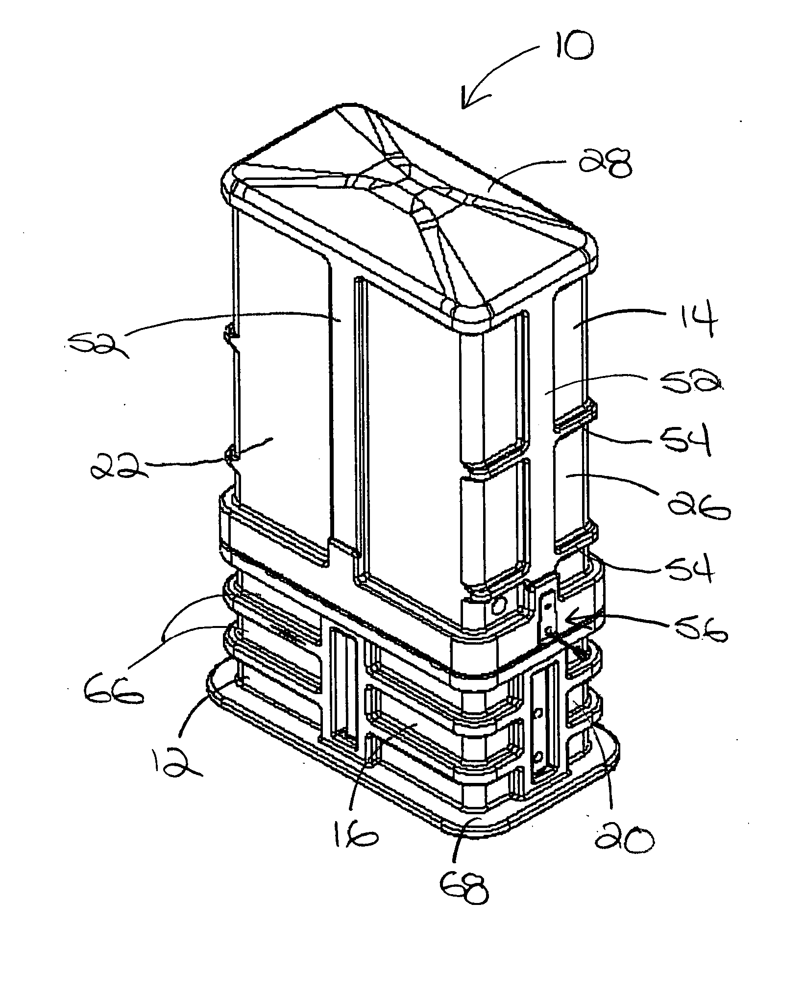
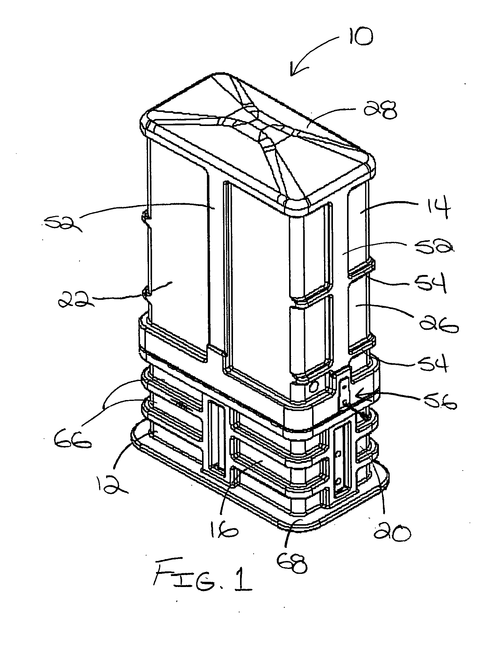
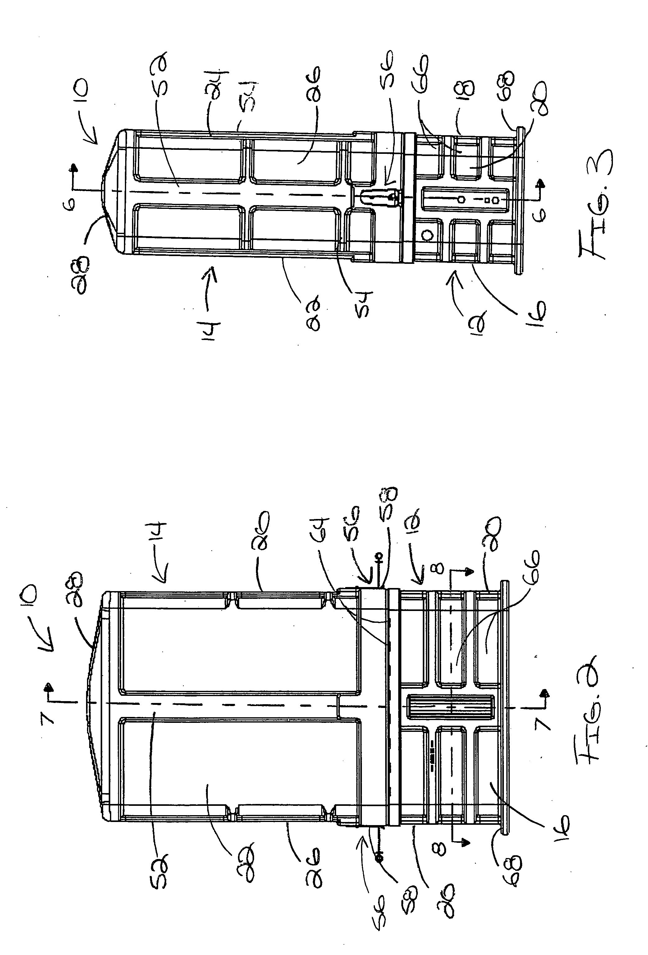
[0028] Referring now to FIGS. 1-4 of the drawings, there is illustrated an exemplary outdoor telecommunications equipment enclosure 10 constructed in accordance with the teachings of the present invention. As described in greater detail below, the enclosure 10 of the present invention has a rugged, substantially weather resistant and weather-tight construction that makes it ideal for outdoor telecommunications applications. Advantageously, the enclosure 10 also has a relatively large volume that makes it particularly applicable to telecommunications applications involving splicing of large pair count cables. Such applications can involve thousands of copper wire splices. The enclosure 10 could also be used at locations in telecommunications systems having both copper wire and fiber optic equipment. For example, the enclosure 10 of the present invention could be configured to accommodate from 1,800 to 3,600 copper splice pairs and / or passive fiber optic equipment. The enclosure 10 co...


PUM


Abstract

The invention provides an outdoor enclosure for housing telecommunications equipment. The enclosure includes a base section having a generally rectangular cross-sectional configuration. The base section is open at an upper end and a lower end and is made of a non-metallic material. The enclosure also includes a single-piece, solid dome having a generally rectangular cross-sectional configuration. The dome has an open lower end of the dome that is engageable with the upper end of the base section so as to define an interior space in the enclosure. The dome is made of a non-metallic material. A latching mechanism is arranged at the upper end of the base section and the lower end of the dome. The latching mechanism is operable to automatically latch the dome and base section together when the dome is arranged on the base section in a predetermined correct orientation. A mounting frame is supported on the base section so as to be arranged in the interior space when the dome is engaged with the base section. The mounting frame has two or more legs and each leg is secured to the base section by at least one fastener. Two or more mounting stakes are attachable to the base section using the fasteners connecting the mounting frame legs to the base section. A bonding / grounding strap is provided that has first and second ends each of which is attachable to a respective one of the legs of the mounting frame. Each of the first and second ends of the bonding / grounding strap has a keyhole slot for receiving a fastener. The keyhole slots having a first portion that is larger than a head of the fastener such that the head can pass through the first portion and a second portion that is smaller than the head of the fastener such that the head is prevented from passing through the slot.

Description

FIELD OF THE INVENTION [0001] This invention pertains to a housing for telecommunications equipment. BACKGROUND OF THE INVENTION [0002] At particular points in telecommunications systems, there is a need to splice large pair count cables. One example of such a point would be branching location where one or more large copper cables are divided into a number of smaller cables. A single branching location could have thousands of copper wire splices. Typically, these splices are housed in large outdoor metal cabinets. Such cabinets can be up to five feet tall, three feet across and one foot deep. These metal cabinets are also used to house large fiber-optic and cable television equipment either separately or in the same enclosure with the copper splices. [0003] The metal cabinets used in these applications generally comprise several pieces of painted galvanized steel that are assembled together with metal hardware to form the cabinet. These cabinets have front doors, and sometimes rear ...

Claims


Application Information

Patent Timeline
Patent Type & Authority Applications(United States)
IPC IPC(8): A47B81/00E04H5/02H02G9/10H05K7/18
CPCE04H5/02H02G9/10H05K7/186
Inventor WITTMEIER, DAVID A.WOODY, LARRY
Owner CHARLES INDS
Why Eureka
Try Eureka