
Dynamic fiber slack management for telecom racks

a fiber slack management and telecom rack technology, applied in the direction of fibre mechanical structures, instruments, optical light guides, etc., can solve the problems of insufficient care for installation and use, the inner core elements of fiber-optic cables are and the cable itself is not designed to be shortened or extended. , to achieve the effect of improving storage and management of excess fiber-optic cables

Inactive Publication Date: 2005-12-15
CIENA
View PDF25 Cites 6 Cited by
  • Summary
  • Abstract
  • Description
  • Claims
  • Application Information

AI Technical Summary

Benefits of technology

[0009] The present invention provides an apparatus and method for improved storage and management of excess amounts of fiber-optic cable for a telecom rack while utilizing minimal space within the telecom rack itself.
[0015] Also convenient under some circumstances is the use of a fiber pass-through means located on a side surface of a telecom equipment component for the passage of fiber-optic cables from their points of connection to the fiber-slack take-up assembly. Furthermore, it may be beneficial to use the fiber pass-through means in conjunction with a fiber spout attached inside the fiber pass-through means whereby the fiber spout provides a minimum bend radius for the fiber-optic cable and protects against abrasion of the fiber-optic cable as the cable traverses the pass-through means.
[0017] As yet another advantage, the fiber-slack take-up assembly comprises retention pins for preventing the fiber-optic cable from slipping off the slack take-up assembly. Furthermore, it may be beneficial to ensure that the retention pins are rotatably mounted to the slack take-up assembly, the retention pins being located in a first position to retain the fiber-optic cable relative to the fiber-slack take-up means, rotatable to a second position to facilitate removal and addition of fiber-optic cable.

Problems solved by technology

The lengths of fiber-optic cables, unlike their copper-based counterparts, are carefully calibrated and therefore the cables themselves are not designed to be shortened or extended by trimming excess cable or splicing together additional cable.
Care must be taken in its installation and use, since the inner core elements of fiber-optic cables are generally small, brittle and may be easily damaged.
Excessive bending of a fiber-optic cable can cause signal loss, reduce the life expectancy of the cable, or even break the inner core of the cable.
Moreover, bending below the minimum bend radius may also damage or break the fiber-optic cable.

Method used


Image

  • Dynamic fiber slack management for telecom racks
  • Dynamic fiber slack management for telecom racks
  • Dynamic fiber slack management for telecom racks

Examples


Embodiment Construction

[0030] The present invention will now be described in more detail with reference to exemplary embodiments thereof as shown in the appended drawings. While the present invention is described below including preferred embodiments, it should be understood that the present invention is not limited thereto. Those of ordinary skill in the art having access to the teachings herein will recognize additional implementations, modifications, and embodiments which are within the scope of the present invention as disclosed and claimed herein. In the figures, like elements are given like reference numbers.

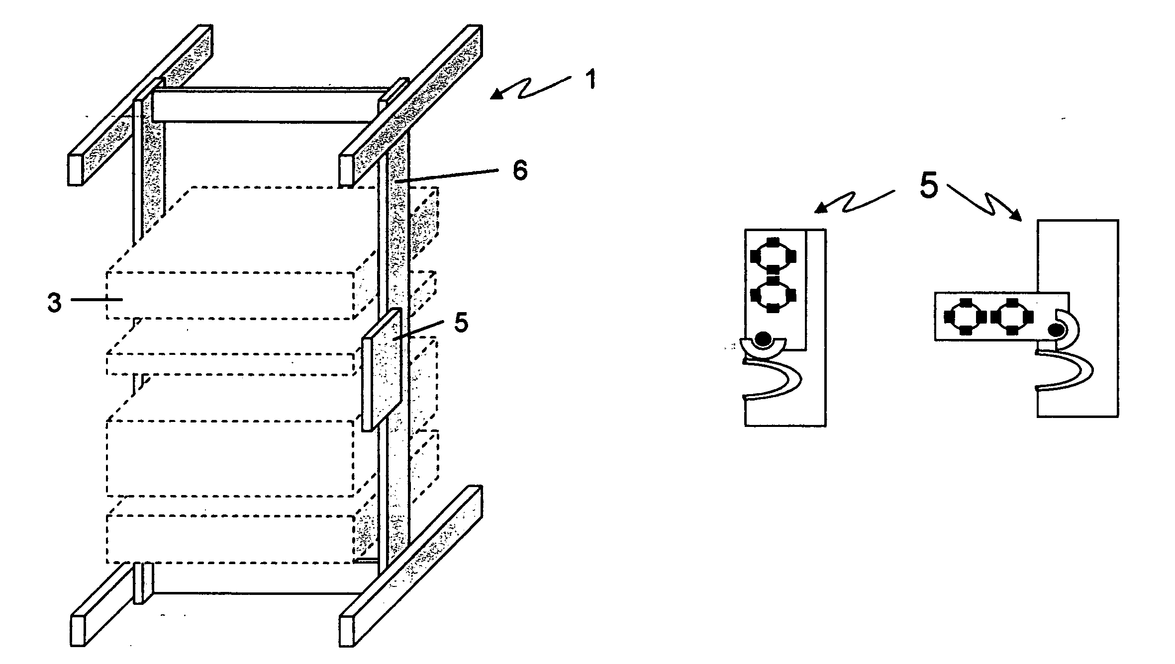
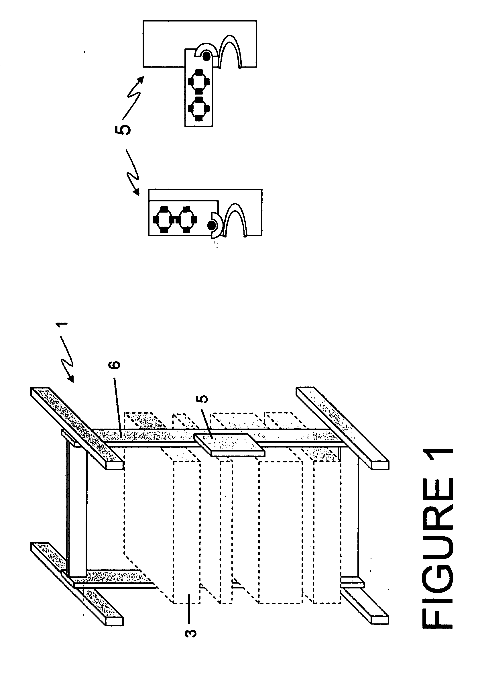
[0031] Referring now to FIG. 1, there is illustrated a typical telecom rack 1 containing an array of telecommunication equipment components 3. Also illustrated is an apparatus 5 for fiber slack management in a telecom rack 1, mounted to a side frame member 6 of the telecom rack 1.

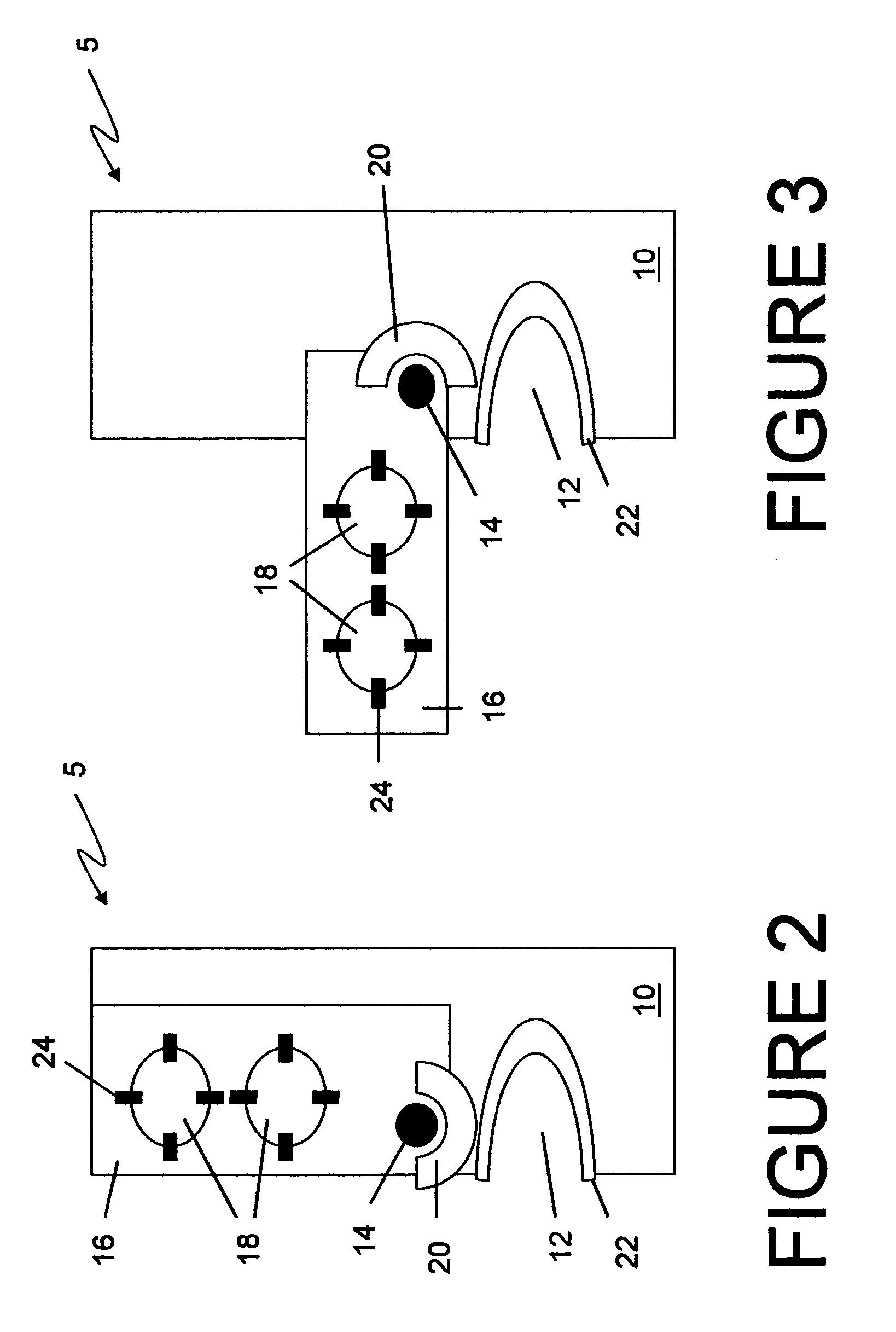
[0032] Referring to FIG. 2, there is illustrated an embodiment of an apparatus 5 for fiber slack management in a te...


PUM


Abstract

Disclosed is an apparatus and method for managing and storing excess amounts of fiber-optic cable in a telecom rack. According to one embodiment, the apparatus comprises a fiber-optic cable slack take-up device attached to an arm. The arm is mounted to a supporting member attached to a side of the telecom rack and movable from a first stored position to a second deployed position. Access to the fiber-slack take-up device is provided by situating the arm in the second position. Situating the arm in the stored position places the slack take-up assembly, along with the excess fiber-optic cable, out of the way of operators working in the equipment aisle. Further embodiments provide means for safe-guarding the minimum bend radius of fiber-optic cable being used. The apparatus and method are useful for overcoming the space requirements of in-rack fiber storage systems known in the art.

Description

FIELD OF THE INVENTION [0001] This invention relates to signal transmission systems in which signals are carried through fiber-optic cables. More particularly, this invention pertains to an apparatus and method for managing and storing excess amounts of fiber-optic cable in a telecom rack. BACKGROUND OF THE INVENTION [0002] The increased use of optical fiber transmission in the telecommunications industry has resulted in a need for the development and installation of fiber-optic transmission systems. [0003] Typically, telecom racks are situated in rows in telecom offices, and define equipment aisles. Telecom racks are used to hold and organize the many telecom equipment components that are required for fiber-optic transmission systems. A great deal of engineering goes into the design of telecom racks in order to combine the most number of components into the least amount of space, while preserving a level of organization, efficiency of use, and maintainability. [0004] Fiber-optic ne...

Claims


Application Information

Patent Timeline
IPC IPC(8): G02B6/00G02B6/44
CPCG02B6/4452G02B6/44524
Inventor AZIZ, FARIDLOW, MICHELEBORTOT, PETERFENKAM, SERGEPACI, CHRISTOPHER
Owner CIENA
Learn More