
Method and system for improved correction of registration error in a fluoroscopic image

a fluoroscopic image and registration error technology, applied in the field of image navigation, can solve the problems of low repeatability, high distortion of intraoperative x-ray images taken by c-arm fluoroscopes alone, and difficulty in accurately determining the position of instruments in objects or environments by visual inspection, etc., to achieve the effect of improving the registration of image and navigation references

Active Publication Date: 2005-12-22
STRYKER EURO OPERATIONS HLDG LLC
View PDF10 Cites 97 Cited by
  • Summary
  • Abstract
  • Description
  • Claims
  • Application Information

AI Technical Summary

Benefits of technology

This patent describes a way to make sure that images taken during medical procedures are accurate. It uses two different tools: one attached to the camera, and another placed on top of the patient's body or around their head. These tools help create precise positions based on which parts of the procedure can be easily identified later on.

Problems solved by technology

The technical problem described in the patent text relates to improving the accuracy of operative procedures involving image-based diagnosis and treatment planning through better alignment of preoperative computed tomography (CT) images with real-time fluorescopy images obtained during surgery. Existing solutions require significant amounts of computational resources and specialized software tools, leading to delays and increased costs. There is also a need for a simpler way to track moving targets within the operating theater.

Method used


Image

  • Method and system for improved correction of registration error in a fluoroscopic image
  • Method and system for improved correction of registration error in a fluoroscopic image
  • Method and system for improved correction of registration error in a fluoroscopic image

Examples


Embodiment Construction

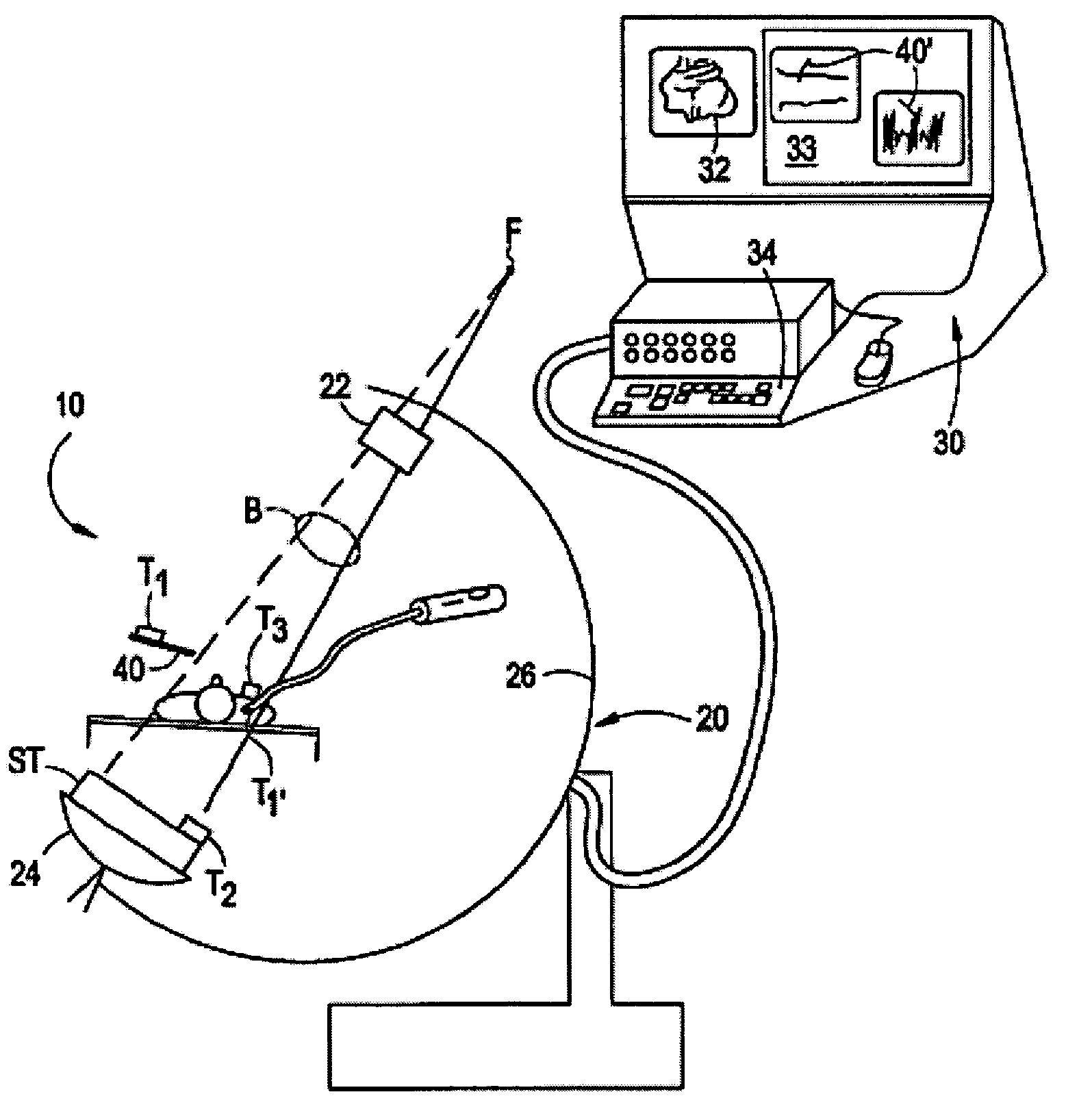
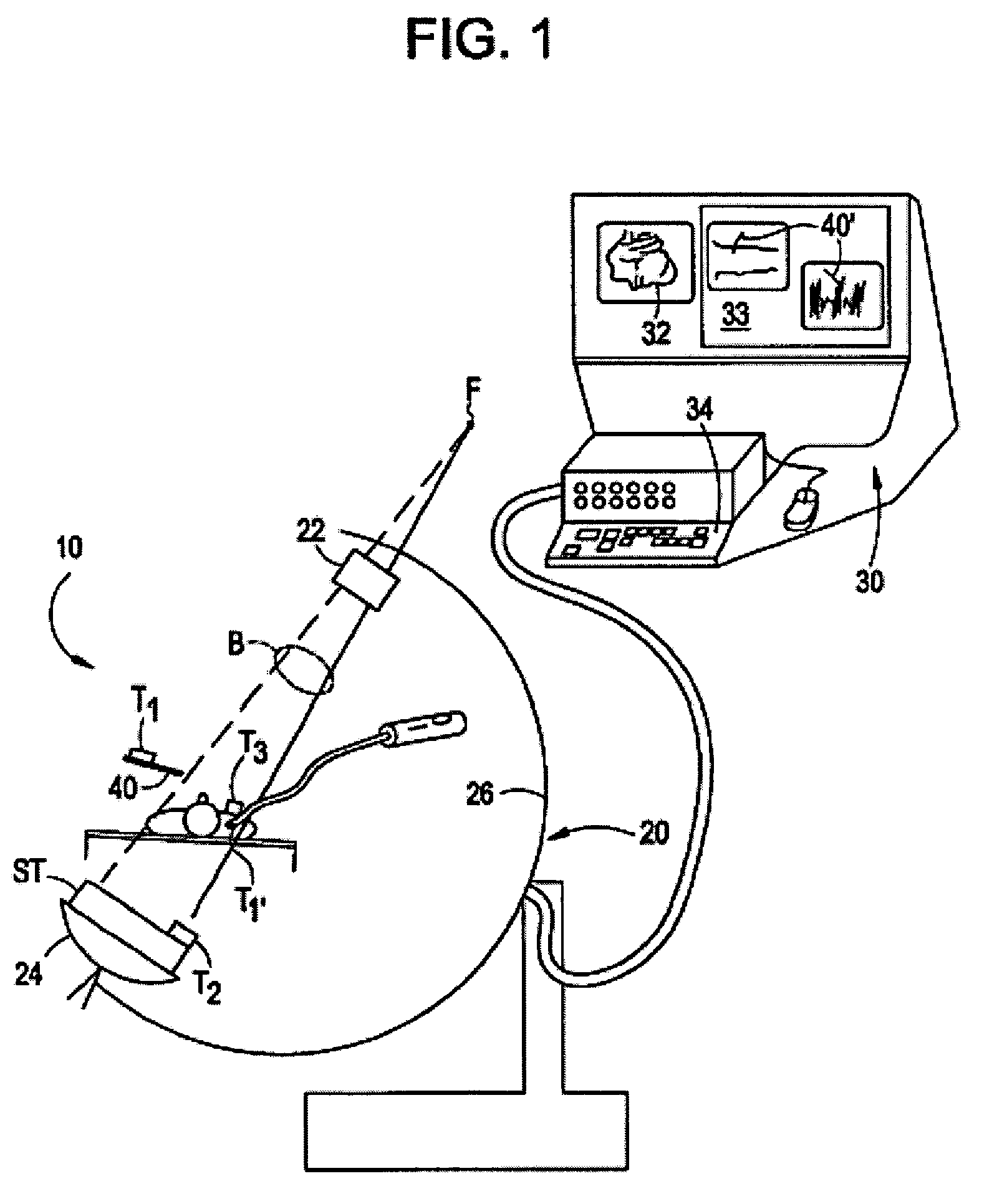
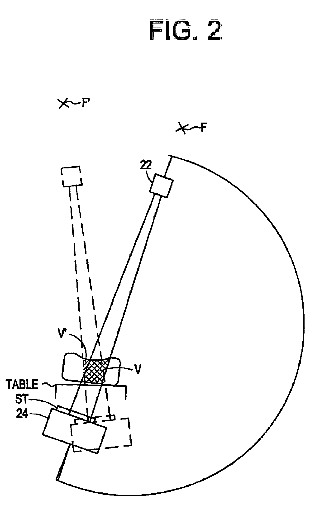
[0043]FIG. 1 illustrates an imaging system 10 in accordance with an embodiment of the present invention for use in an operating room environment. As shown in FIG. 1, the system 10 includes a fluoroscope 20, a work station 30 having one or more displays 32 and a keyboard / mouse or other user interface 34, and a plurality of tracking elements T1, T2, T3. The fluoroscope 20 is illustrated as a C-arm fluoroscope in which an x-ray source 22 is mounted on a structural member or C-arm 26 opposite to an x-ray receiving and detecting unit, referred to herein as an imaging assembly 24. The C-arm moves about a patient or other object to produce two dimensional projection images of the patient from different angles. The patient or object remains positioned between the source and the camera, and may, for example, be situated on a table or other support, although the patient / object may move. The tracking elements, described further below, are mounted such that one element T1 is affixed to, incorpo...


PUM


Abstract

Certain embodiments of the present invention provide a method and system for improved registration of image and navigation references used in image-guided operations. Certain embodiments of the system include an image acquisition device for obtaining at least one image of an object, a first calibration fixture positioned in relation to the image acquisition device, and a second calibration fixture positioned in relation to the object. The position data from first calibration fixture is used to form a characterization of the image acquisition device, which is corrected by position data from the second calibration fixture. In an embodiment, a first calibration fixture is affixed to a C-arm camera and a smaller second calibration fixture is affixed to a patient. Data from the first and second calibration fixtures is used with tracking data to calibrate the image acquisition data and register reference points in image and navigation reference frames.

Description


Claims


Application Information

Patent Timeline
Owner STRYKER EURO OPERATIONS HLDG LLC
Learn More