
Image processing device and method, recording medium, and program

a processing device and image technology, applied in image enhancement, image analysis, instruments, etc., can solve the problems of deteriorating image quality and and achieve the effect of reducing blur easily and not placing a great burden on the user

Inactive Publication Date: 2005-12-22
SONY CORP
View PDF5 Cites 19 Cited by
  • Summary
  • Abstract
  • Description
  • Claims
  • Application Information

AI Technical Summary

Benefits of technology

[0010] The present invention has been made in light of the above problems, and provides for correction of blurring easily without placing a great burden on the user.
[0023] According to the first to the fourth aspect of the present invention, the blurring of an image can be corrected. Specifically, according to the present invention, the blurring of an image can be corrected easily without placing a particular burden on the user.
[0024] According to the fifth to the eighth aspect of the present invention, a table can be created wherein the parameters for correcting an image are listed. Specifically, a table can be created wherein the parameters for easily correcting an image, without placing a particular burden on the user, are listed.

Problems solved by technology

However, in the event that processing is performed to correct the blurring of the entire image, for example, the blurring of the image of the main object is corrected, but the drawback is that overshooting or ringing can occur in the background image that was not blurred until that point in time, and the resulting image is of a deteriorated quality.
However, if the area of the correcting region is to be determined by the user, in the case that the shape of the main object has a complicated shape, for example, an operation is necessary wherein the periphery of the object with a complicated shape is traced precisely, and this places a great burden on the user.

Method used

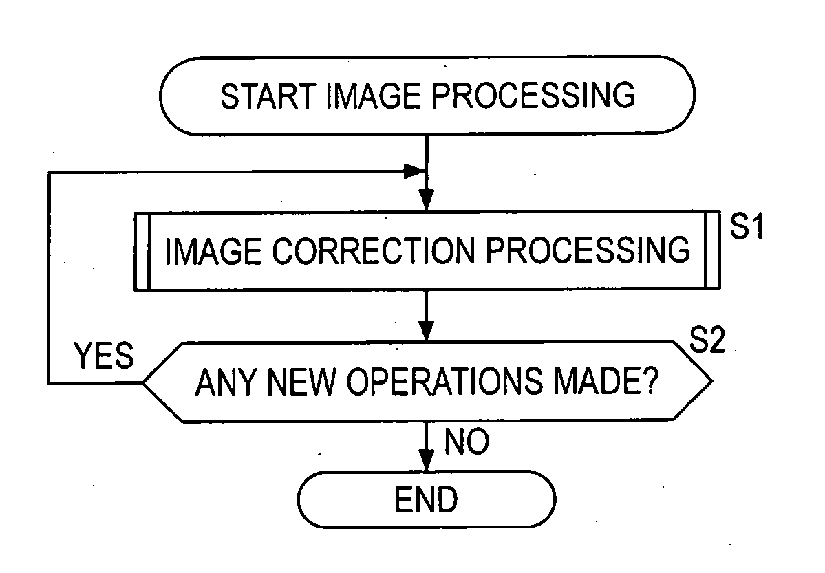
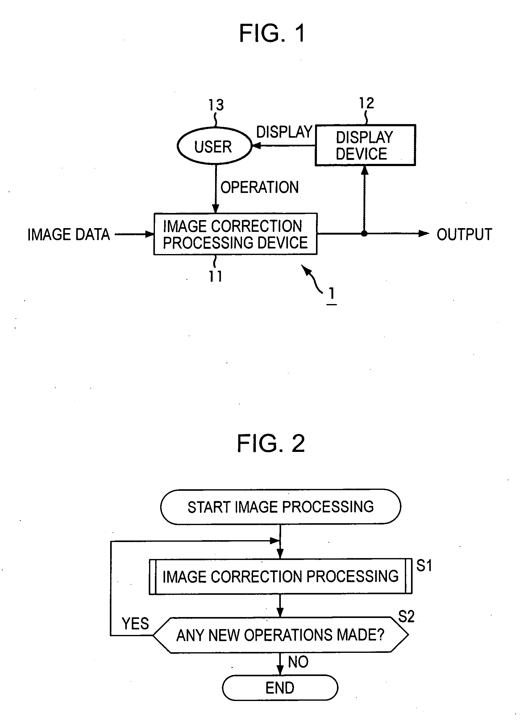
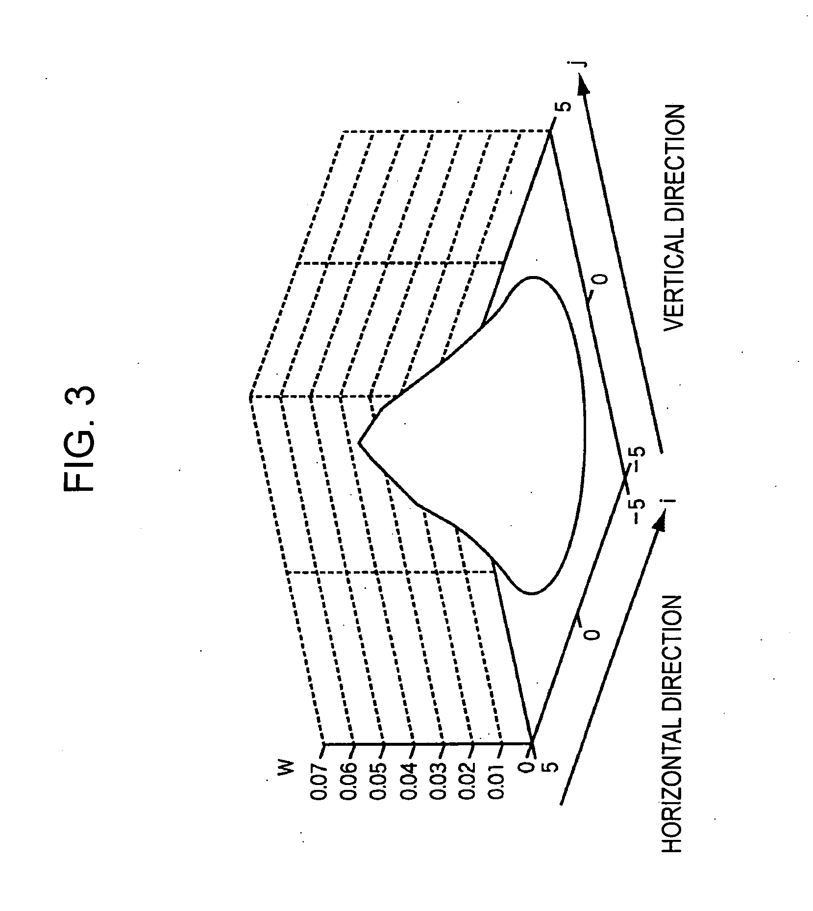

Image

  • Image processing device and method, recording medium, and program
  • Image processing device and method, recording medium, and program
  • Image processing device and method, recording medium, and program

Examples


Embodiment Construction

[0060] The preferred embodiments of the present invention will be described below, and the corresponding relationship between the invention disclosed and the embodiments thereof is as follows. Even in the event that an embodiment is described in the specification but is not described as being an embodiment that is applicable to the invention, this does not necessarily mean that the embodiment is not applicable to the invention. Conversely, even in the event that an embodiment is described here as being applicable to the invention, that does not mean that this embodiment is not applicable to an invention other than this invention.

[0061] Further, this description does not mean the invention in its entirety that is described in the specification. In other words, this description is the invention that is described in the specification, and is not to deny any invention that is not claimed in this application, that is, any additional inventions occurring due to future filing of divisiona...


PUM


Abstract

A user interface unit sets a parameter based on operations of a user, and outputs to a parameter correction unit. The parameter correction unit extracts the feature quantity of pixels in an observation region that corresponds to the value of the parameter, and based on the maximal value of that feature quantity, corrects the parameter specified by the user as the correction parameter. A blurring correction unit corrects input image data based on the correction parameter, and generates image data of the image wherein the blurring has been corrected. The present invention can be applied, for example, to a digital camera.

Description

BACKGROUND OF THE INVENTION CROSS-REFERENCE TO RELATED APPLICATIONS [0001] The present application is related to Japanese Patent Application Nos. JP2004-173086, filed Jun. 10, 2004, and JP2005-159397, filed May 31, 2005. The entire contents of each of the above-identified patents are incorporated herein by reference. [0002] 1. Field of the Invention [0003] The present invention relates to an image processing device and method, a recording medium, and a program, and specifically relates to an image processing device and method, a recording medium, and a program whereby blurring of an image due to being out of focus can be corrected. [0004] 2. Discussion of the Background [0005] Recently, digital cameras have come into widespread use, and opportunities have increased for many users to take photographs. Digital cameras have a so-called auto-focus function, wherein the appropriate focus adjustment is made with regard to a subject by the camera. [0006] However, with the auto-focus functi...

Claims


Application Information

Patent Timeline
IPC IPC(8): G06T5/00
CPCG06T2200/24G06T2207/20201G06T5/003G06T5/73G06T7/00
Inventor SHIRAKI, HISAKAZUKONDO, TETSUJIRO
Owner SONY CORP
Learn More