Three dimensional monitor and tactile scanner

a three-dimensional monitor and scanner technology, applied in the direction of identification means, instruments, display means, etc., can solve the problem of not being able to commercially viable true three-dimensional displays, and achieve the effect of accurate color images of objects being displayed

Inactive Publication Date: 2002-10-08
KRAVTSOV GRIGORY
View PDF4 Cites 93 Cited by
  • Summary
  • Abstract
  • Description
  • Claims
  • Application Information

AI Technical Summary

Benefits of technology

Described in the patent to Sachs is a system for producing three dimensional components by bonding together successive layers of a porous material with droplets of a binder material. A binder printhead has an array of nozzles which controllably supply jets of binder material droplets to the layers of porous material. The printhead is scanned in a raster scan fashion over each layer of porous material along a first scan axis in one direction to provide first fast scanning paths of droplets. The printhead is then moved laterally of such one direction and is then moved along the fast-scan axis in the opposite direction to provide second fast scanning paths of droplets which are interlaced with the first scanning paths. The supply of the droplets to the porous material can be controlled so as to control the overlapping thereof to produce various desired surface and interior characteristics of the components.
In a first embodiment, a rectangular grid of pins is connected to a control circuit to move the pins independently of each other to form a predetermined contour based on an input signal. The pins can move in at least one direction to approximate the shape of an three dimensional object described in a digital file ("digital image"). The pins also contain an array of lighting elements such as LEDs or fiber optic lights to present an accurate color image of the object being displayed. The combination of the three dimensional contour and color display in the three dimensional grid for a three dimensional replication of the original object in real time. The display can be viewed to appreciate the three dimensional character of the display, and can be touched and felt to provide tactile feedback to the viewer.
The display can be covered in a latex or similar material to enhance the sense of feel to the display. The cover material also provides a moisture and dust barrier to the device and can be used in conjunction with the light sources to enhance the display. In a preferred embodiment, the sense of feel is further enhanced by providing the pins with an adjustable hardness that can be controlled by the signal to further enhance the tactile response by the viewer. The temperature of the individual rods can also be controlled in response to a control signal by electrical heating or cooling of the elements to further enhance the tactile response.
Accordingly, it is a principal object of the invention to provide a three dimensional display that can simulate the contour and texture of a image from a digital representation of that object.
It is an object of the invention to provide improved elements and arrangements thereof in an apparatus for the purposes described which is inexpensive, dependable and fully effective in accomplishing its intended purposes.

Problems solved by technology

However, there are no commercially viable true three-dimensional displays that can display both the image and contour of an object in real time.

Method used


Image

  • Three dimensional monitor and tactile scanner
  • Three dimensional monitor and tactile scanner
  • Three dimensional monitor and tactile scanner

Examples


first embodiment

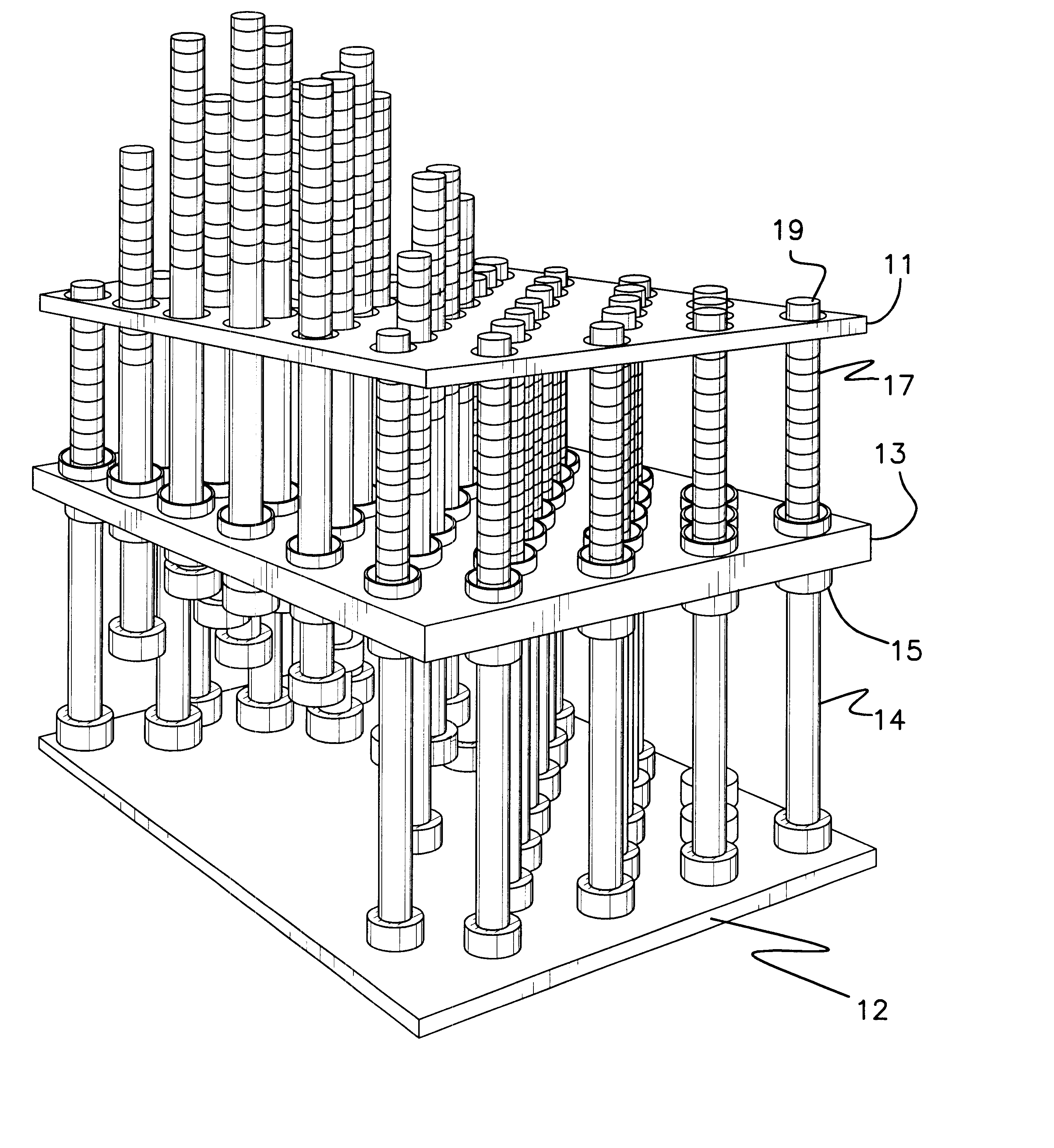
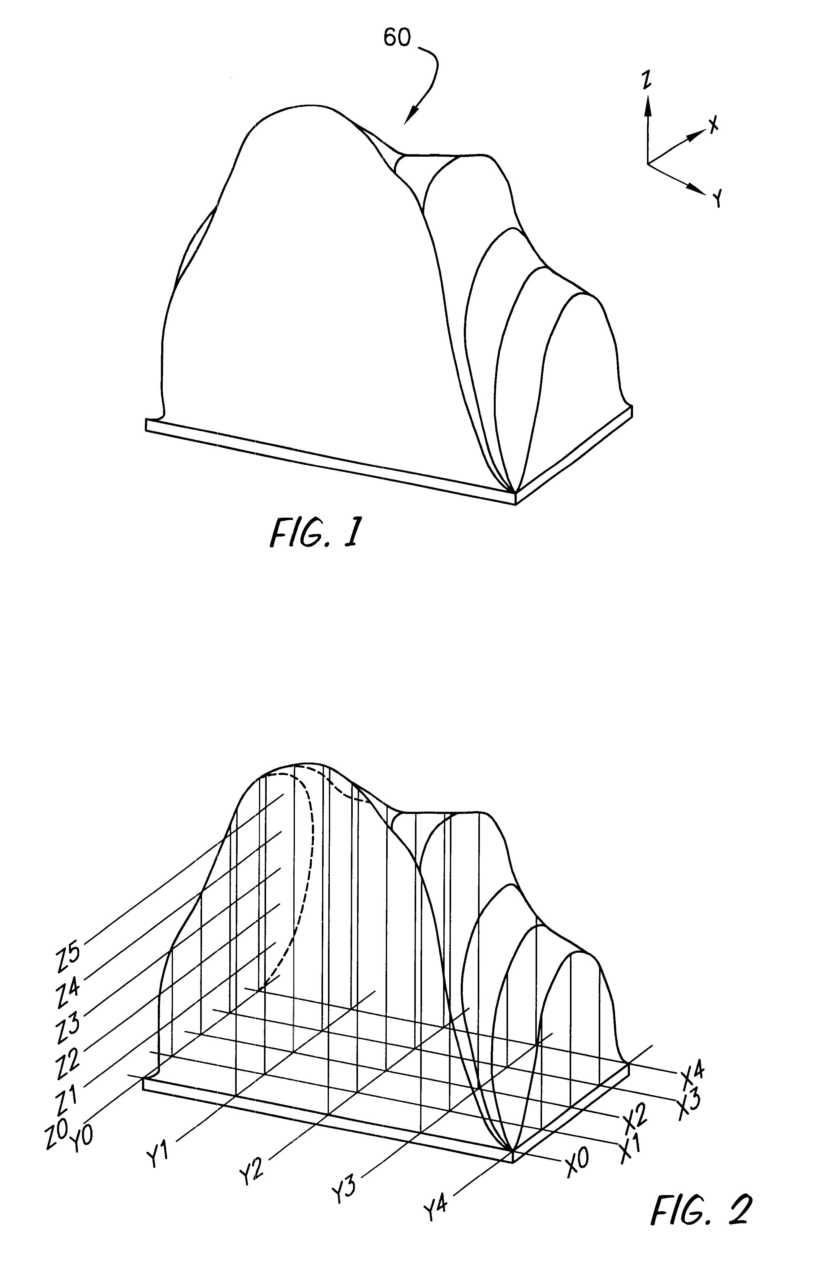
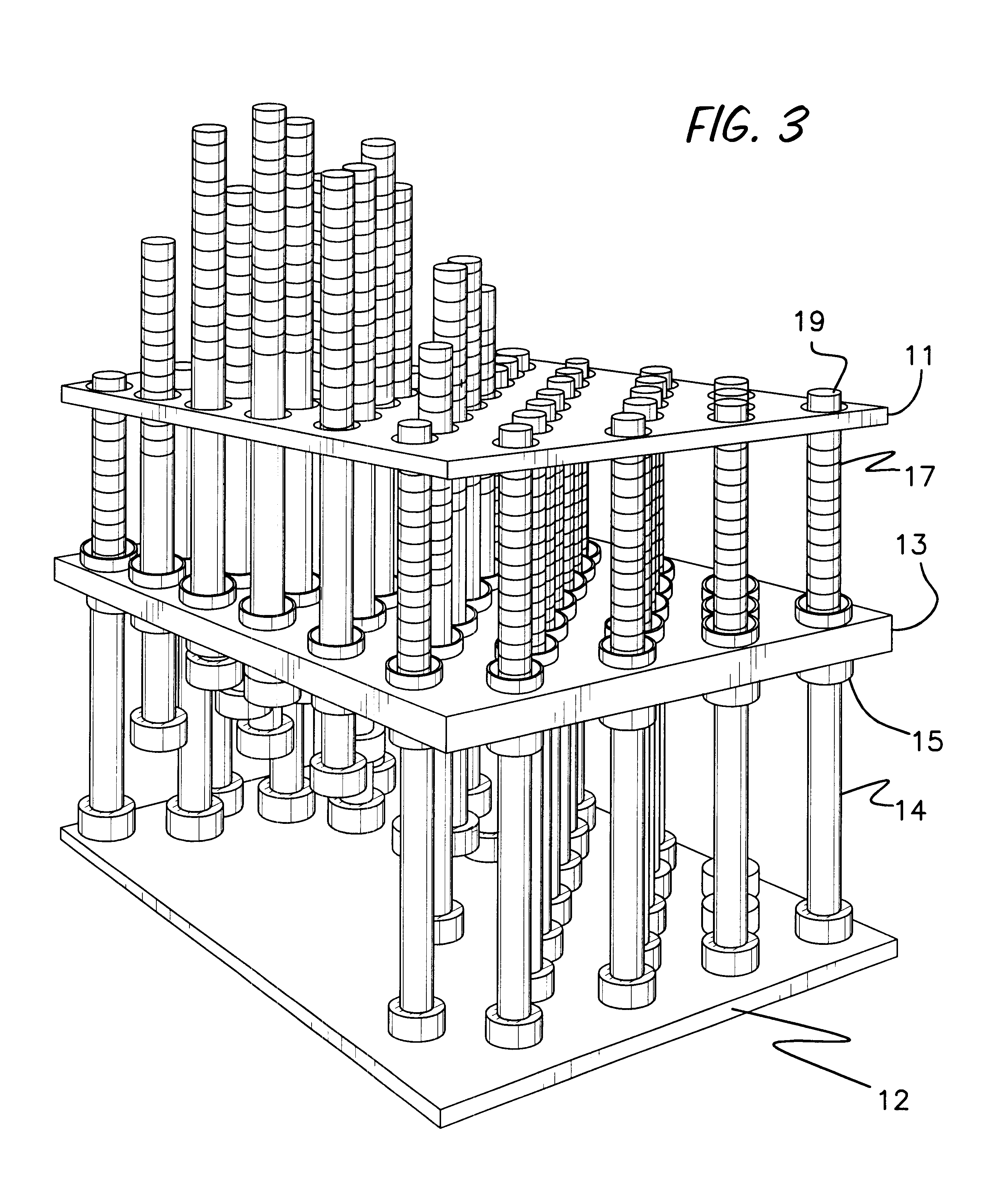
One embodiment of a display capable of presenting this information is shown in FIGS. 3 through 7, as will be described herein. the invention describes a real time method of displaying not only the image of the object, but also its contour and shape and other features in real time in a format that can be changed and altered to display multiple sequential models or a model in motion.

As shown in FIGS. 3 through 7, a three-dimensional display unit 62 includes a plurality of rods ("display elements") 14 as shown in FIG. 3. The display elements are cylindrical in shape and spaced closely together to form a matrix of six rows by four columns with each alternate row offset for maximum fill in. This shape is shown by way of example only and could be arranged in any number of rows, columns, or other geometric patterns to provide the desired resolution and spacing of the display elements. The number of rows and columns and the spacing should be determined by the accuracy needed ("resolution") ...

third embodiment

the invention is shown in FIG. 14. In this embodiment the display is formed of a number of transparent panels 140 of LED lights 142 capable of displaying red, green and blue pixels in rows and columns across each panel 140. When the panels are mounted together, a three dimensional matrix of pixels is formed capable of displaying a three dimensional model of an object. The display utilizes transparent wiring as discussed above to further enhance light transmission through and out of the display. The LEDs 142 are sized and made be constructed so as to minimize disruption of light flow through the display. In this way an object can be displayed by displaying the contour of the modeled object at the appropriate LED location as discussed above in a near hologram fashion. Through appropriate software, the model can be rotated or cross-sectioned, etc. to increase the diagnostic and educational value of the model.

FIGS. 15 and 16 show an alternative embodiment of a three-dimensional display ...


PUM


Abstract

A three-dimensional display system including a method of operating the display as a tactile scanner. A three dimensional display is formed from a number of moveable rods arranged in a matrix. Each rod has selectively illuminated pixels made from LEDs or similar devices. The rods can be moved independent to position the pixels into position to model a pre-defined object to present a three-dimensional model and overlaying image. The pixels can also be illuminated by an external lighting source such as a laser. Stationary embodiments of the monitor are also disclosed which are formed of a three dimensional grid of LEDs or other light sources which can be selectively illuminated to provide a true three dimensional display.

Description

1. Field of the InventionThe present invention is to a three-dimensional monitor and tactile scanner for transmitting, storing, and displaying three dimensional models.2. Description of the Prior ArtAs computers play an increasingly important role in our lives, unlimited numbers of two dimensional displays are presented to us in many diverse forms such as computer monitors, television screens, calculators, and digital watch faces. As computers continue to be integrated into the entertainment industry, many of these displays are built to provide a three dimensional effect by overlapping displays of blue, green and red slightly offset from each other to give a feeling of "depth" to the display. Some devices such as the "Three-D glasses" have been used to project a sense of depth to the screen in a similar manner.However, there are no commercially viable true three-dimensional displays that can display both the image and contour of an object in real time. The present invention provides...

Claims


Application Information

Patent Timeline
Patent Type & Authority Patents(United States)
IPC IPC(8): G09F13/22G09F9/33H04N13/00
CPCG09F9/33G09F13/22H04N13/0422H04N13/0488H04N13/0497G06F3/016H04N1/04H04N13/324H04N13/388H04N13/398
Inventor KRAVTSOV, GRIGORY
Owner KRAVTSOV GRIGORY
Why Eureka
Try Eureka