Real image forming eye examination lens utilizing two reflecting surfaces providing upright image

a technology of eye examination and reflection, applied in the field of ophthalmoscopic lenses, can solve the problems of excessive weight, large lens length, and small field of view obtainable through each mirror, and achieve the effects of avoiding complexity of design and manufacturing, easy positioning and manipulation, and excellent optical attributes

Inactive Publication Date: 2009-07-23
VOLK DONALD A
View PDF7 Cites 94 Cited by
  • Summary
  • Abstract
  • Description
  • Claims
  • Application Information

AI Technical Summary

Benefits of technology

[0008]Based on the foregoing there is found to be a need to provide a real image forming gonioscopy lens that avoids the problems associated with the prior art lenses and which in particular provides a correctly oriented image of the structures of the eye, has excellent optical attributes, is easily positioned and manipulated within the orbital area of the examined eye and which avoids complexity of design and difficulty of manufacture. It is therefore a main object of the invention to provide an improved diagnostic and therapeutic gonioscopy lens that incorporates two reflecting surfaces that combine to provide positive power contributing to the formation of a real image that is correctly oriented with respect to the structures of the eye.

Problems solved by technology

Furthermore the field of view obtainable through each mirror is very small.
Although achromatized and somewhat corrected for other aberrations, the lenses depicted in the embodiments of the 111 patent to Ross exhibit numerous disadvantages that preclude its successful application, including excessive weight, an excessive lens length of over 35 mm, an excessive distance from the examined eye to the image plane of over 51 mm, which is beyond the positioning range of the slit lamp biomicroscope, and poor stereoscopic visualization and image scanning capability resulting from the small light ray footprint at the biomicroscope objective lens aperture.

Method used


Image

  • Real image forming eye examination lens utilizing two reflecting surfaces providing upright image
  • Real image forming eye examination lens utilizing two reflecting surfaces providing upright image
  • Real image forming eye examination lens utilizing two reflecting surfaces providing upright image

Examples


first embodiment

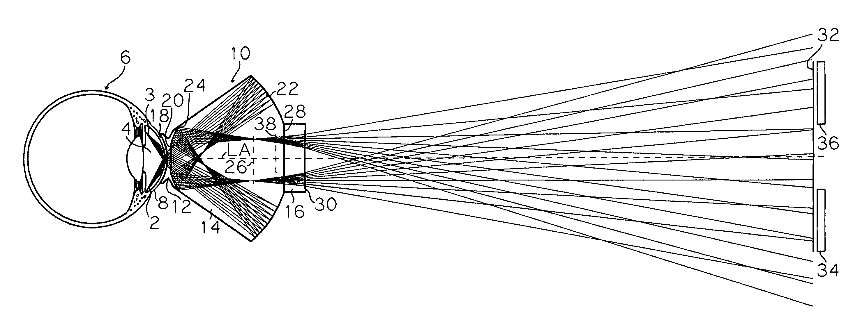
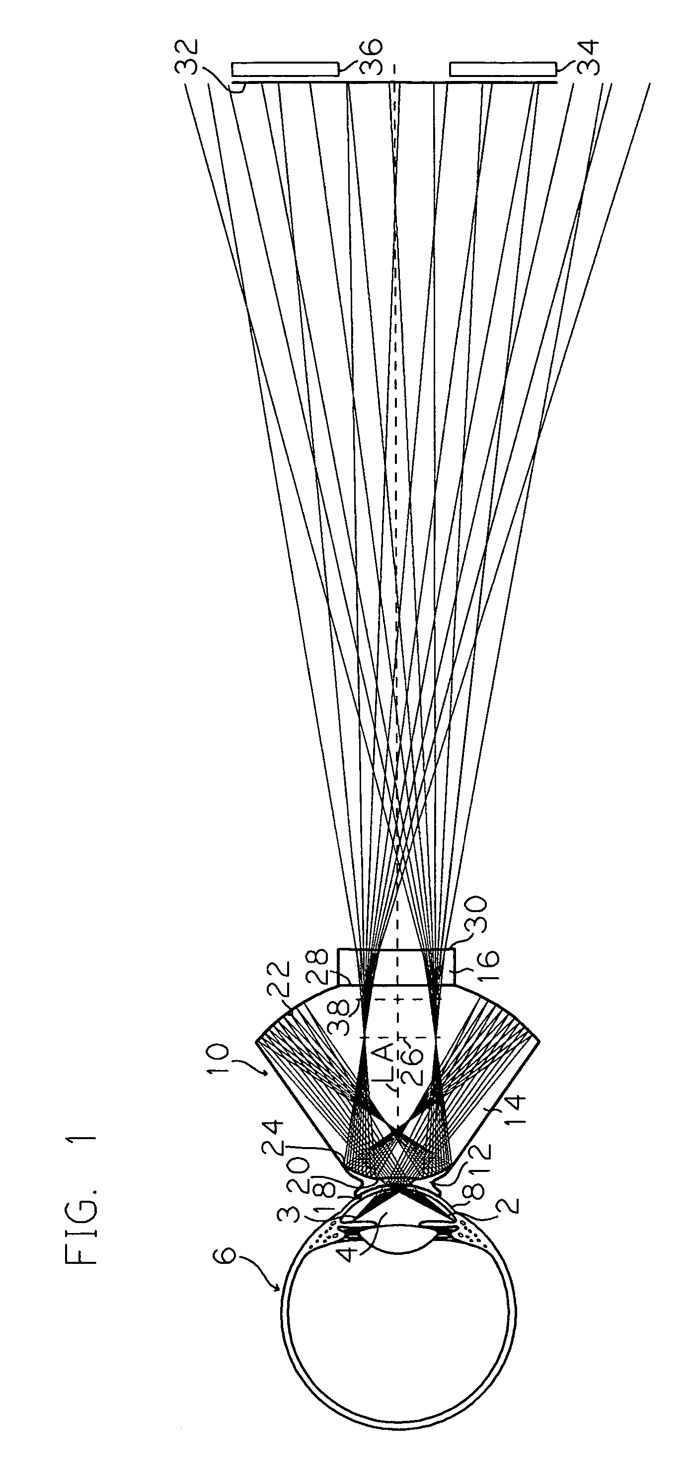
[0043]Referring to FIG. 1, there is shown a ray tracing and schematic cross-sectional view of an exemplary triplet gonioscopy lens according to the invention, wherein lens 10 comprises an optically coupled lens including posterior contacting element 12, intermediate reflecting element 14 and anterior cap element 16. In this embodiment the anterior reflecting surface comprises an aspheric curvature and the posterior reflecting surface comprises a spherical curvature. Posterior element 12 is made of optical quality polymethylmethacrylate with an index of refraction of approximately Nd=1.492 and an Abbe number of approximately Vd=55.3, intermediate element 14 is made of S-LAH58 optical glass (available from Ohara Corp.) having an index of refraction of approximately Nd=1.883 and an Abbe number of approximately Vd=40.8, and anterior element 16 is made of N-BK7 (available from Schott AG) having an index of refraction of approximately Nd=1.517 and an Abbe number of approximately Vd=64. Th...

second embodiment

[0061]Referring to FIG. 3, there is shown a ray tracing and schematic cross-sectional view of an exemplary triplet gonioscopy lens according to the invention, wherein lens 40 comprises an optically coupled lens including posterior contacting element 42, intermediate reflecting element 44 and anterior cap element 46. In this embodiment both the anterior and posterior reflecting surfaces comprise aspheric curvatures and both are non-lenticulated surfaces. Posterior element 42 is made of optical quality polymethylmethacrylate, intermediate element 44 is made of S-LAH58 optical glass and anterior element 46 is made of N-BK7. The three elements 42, 44 and 46 are optically coupled at their respective interfaces using suitable coupling materials as previously described. Referring to FIG. 3, light rays of ray bundles 2b and 3b emanating from the stated iridocorneal and peripheral iris locations of anterior chamber 4b of eye 6b pass through the cornea 8b and tear layer of the eye and enter p...

third embodiment

[0064]Referring to FIG. 4, there is shown a ray tracing and schematic cross-sectional view of an exemplary doublet gonioscopy lens according to the invention, wherein lens 70 comprises an optically coupled lens including posterior contacting and reflecting element 72 and anterior cap element 74. In this embodiment the anterior reflecting surface comprises an aspheric curvature and the posterior reflecting surface comprises a spherical curvature. Posterior element 72 is made of S-LAH58 optical glass and anterior element 74 is made of N-BK7. The two elements 72 and 74 are optically coupled at their interface using a suitable coupling material as previously described. Referring to FIG. 4, light rays of ray bundles 2c and 3c emanating from the stated iridocorneal and peripheral iris locations of anterior chamber 4c of eye 6c pass through the cornea 8c and tear layer of the eye and enter posterior contacting element 72 of lens 70 through corneal contacting surface 76 and continue to conc...


PUM


Abstract

A diagnostic and therapeutic contact lens is provided for use with biomicroscopes for the examination and treatment of structures of the eye. The lens comprises a contacting surface adapted for placement on the cornea of an eye, two reflecting surfaces, and a refracting surface. A light ray emanating from the structure of the eye enters the lens and contributes to the formation of a correctly oriented real image. The light ray is reflected in an ordered sequence of reflections, first as a negative reflection in a posterior direction from an anterior reflecting surface and next as a positive reflection in an anterior direction from a posterior reflecting surface. The light ray contributes to forming the image of the structure of the eye either anterior to the lens or within the lens and proceeds along a pathway to the objective lens of the biomicroscope used for stereoscopic viewing and image scanning.

Description

PRIORITY CLAIM[0001]This application claims priority to, and the full benefit of, U.S. Provisional Patent Application No. 61 / 062,004, titled “REAL IMAGE FORMING EYE EXAMINATION LENS UTILIZING TWO REFLECTING SURFACES PROVIDING UPRIGHT IMAGE” and filed Jan. 22, 2008, which is incorporated by reference in its entirety.BACKGROUND OF THE INVENTION[0002]1. Field of the Invention[0003]The lens of the present disclosure relates to ophthalmoscopic lenses for use with the slit lamp or other biomicroscope. More particularly the invention relates to diagnostic and therapeutic gonioscopic and indirect ophthalmoscopic contact lenses that incorporate two reflecting surfaces which combine to provide positive power contributing to the formation of a real and correctly oriented image of the examined structures of the eye anterior of the lens or within the lens or element of the lens while optimally directing the light rays to the objective lens of the slit lamp biomicroscope for stereoscopic viewing ...

Claims


Application Information

Patent Timeline
Patent Type & Authority Applications(United States)
IPC IPC(8): A61B3/125A61B3/14
CPCA61B3/125A61F9/0017G02B17/086G02B17/0812G02B17/0808A61B3/117
Inventor VOLK, DONALD A.
Owner VOLK DONALD A
Why Eureka
Try Eureka