Multi-hedral rotary wing

a rotary wing and multi-hedral technology, applied in the field of aerodynamic structures, can solve the problems of increasing the stress in the blade structure, reducing the degree of anhedral, and affecting the performance of the forward flight performance of the rotor blade, so as to reduce the influence of the tip vortex, improve the hover performance, and improve the effect of hover performan

Inactive Publication Date: 2005-12-22
SIKORSKY AIRCRAFT CORP
View PDF9 Cites 23 Cited by
  • Summary
  • Abstract
  • Description
  • Claims
  • Application Information

AI Technical Summary

Benefits of technology

[0005] The rotary-wing according to the present invention provides a multi-hedral tip section which utilizes a distribution of anhedral and/or dihedral angles that cause a tip vortex to be axially displaced relative to the region on the following blade strongly impacted by the tip vor

Problems solved by technology

Although anhedral relatively improves hover performance, anhedral may have negative performance tradeoffs in forward flight performance.
Moreover, the degree of anhedral is generally limited by structural considerations associated

Method used


Image

  • Multi-hedral rotary wing
  • Multi-hedral rotary wing
  • Multi-hedral rotary wing

Examples


Embodiment Construction

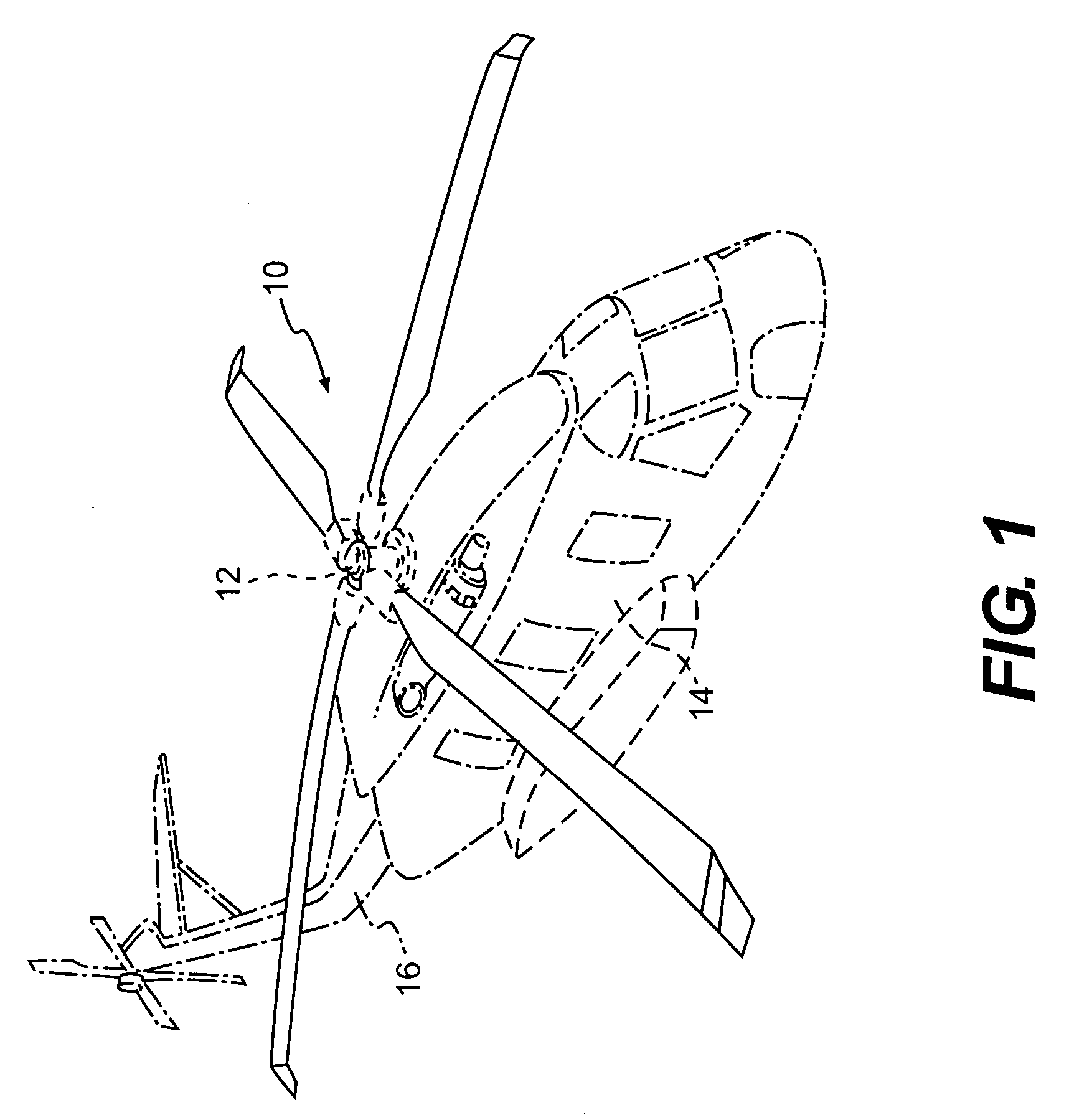
[0020]FIG. 1 schematically illustrates a rotary-wing aircraft 10 having a main rotor assembly 12. The aircraft 10 includes an airframe 14 having an extending tail 16 which mounts an anti-torque rotor 18. Although a particular helicopter configuration is illustrated in the disclosed embodiment, other machines such as turbo-props, tilt-rotor and tilt-wing aircraft will also benefit from the present invention.

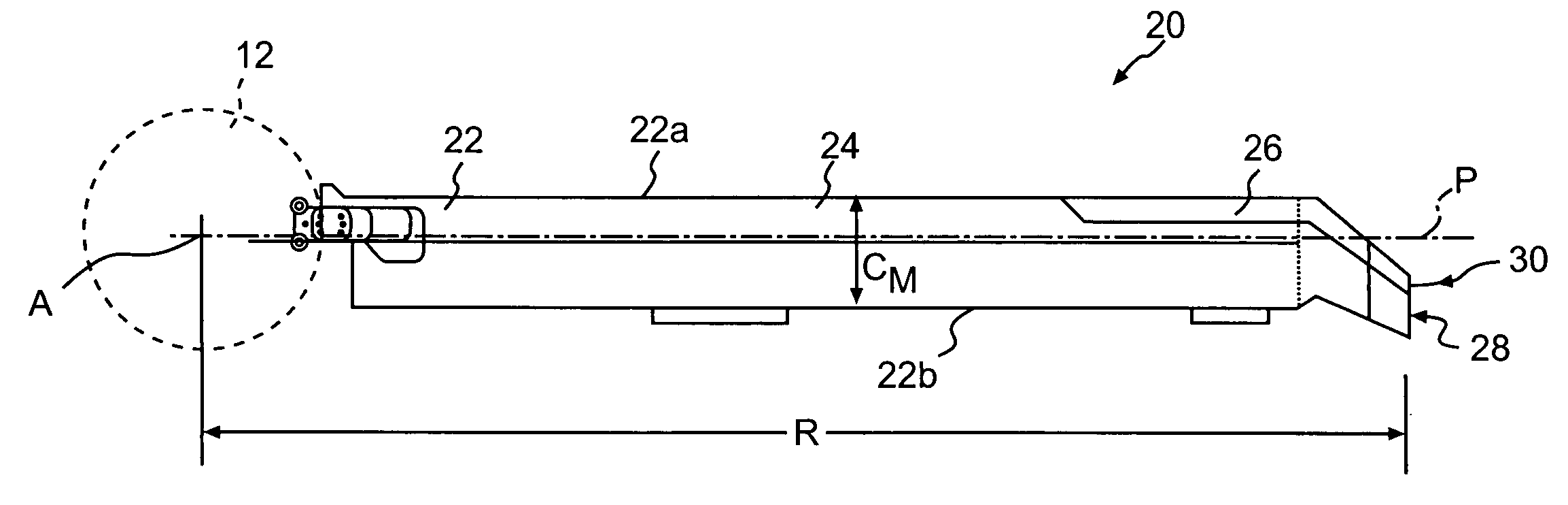
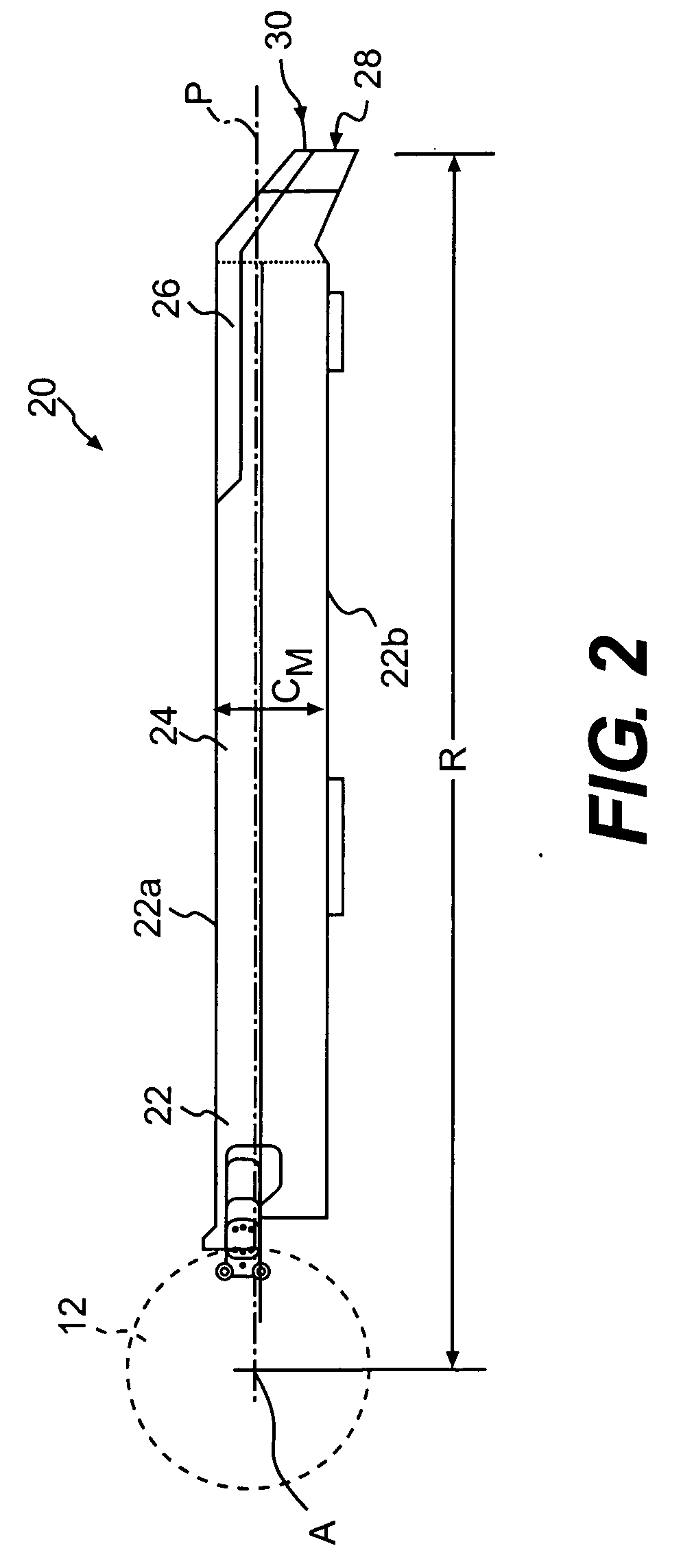
[0021] Referring to FIG. 2, a rotor blade 20 (only one illustrated) of the rotor assembly 12 includes an inboard section 22, an intermediate section 24, and an outboard section 26. The inboard, intermediate, and outboard sections 22, 24, 26 define the span of the main rotor blade 20. The rotor blade sections 22, 24, 26 define a blade radius R between the axis of rotation A and a distal end 30 of a blade tip section 28.

[0022] The blade root portion 22 is attached to the rotor assembly 12 for rotating the rotor blade 20 about the axis of rotation A and for pitching about a longitu...


PUM


Abstract

A rotary-wing includes a multi-hedral tip section which utilizes a distribution of anhedral and/or dihedral angles that cause a tip vortex to be axially displaced relative to a region on a following blade such that the tip vortex generally avoids influence upon the following blade.

Description

BACKGROUND OF THE INVENTION [0001] The present invention relates to aerodynamic structures, and more particularly to multi-hedral rotor blade, which reduces tip vortex influence on a following blade. [0002] Aerodynamic surfaces produce tip vortices as an artifact of flow. During typical rotorcraft flight operations, rotor blades of a main rotor assembly, due to the airfoil profile and angle of attack of the rotor blades, create a high velocity low pressure field over the upper aerodynamic surface of each rotor blade and a low velocity high pressure field over the lower aerodynamic surface of each rotor blade. At the tip of each rotor blade, this pressure differential effectively engenders airflow circulation from the high pressure field to the low pressure field to create a tip vortex. [0003] During rotorcraft flight operations, the tip vortex is shed from a preceding rotor blade and at least partially interferes with a following rotor blade. Hover performance of helicopter rotors a...

Claims


Application Information

Patent Timeline
IPC IPC(8): B63H1/26B64C27/46
CPCB64C27/463
Inventor EGOLF, THOMAS A.MOFFITT, ROBERT
Owner SIKORSKY AIRCRAFT CORP
Why Eureka
Try Eureka