Shielding configuration for a multi-port jack assembly

a multi-port jack and shielding technology, applied in the direction of coupling devices, electrical equipment, coupling devices, etc., can solve the problems of large volume within the assembly, insufficient signal conditioning devices, and network operation at 1 gigabit speed, and require significant signal conditioning

Inactive Publication Date: 2005-12-22
TE CONNECTIVITY CORP
View PDF6 Cites 34 Cited by
  • Summary
  • Abstract
  • Description
  • Claims
  • Application Information

AI Technical Summary

Problems solved by technology

Therefore, the volume within the assembly is inadequate to provide the proper signal conditioning devices for the high speeds now required.
Furthermore, such networks now operate at speeds of 1 gigabit and higher which requires significant conditioning to the signals.
While the technology exists for conditioning the signals, no connect

Method used


Image

  • Shielding configuration for a multi-port jack assembly
  • Shielding configuration for a multi-port jack assembly
  • Shielding configuration for a multi-port jack assembly

Examples


Embodiment Construction

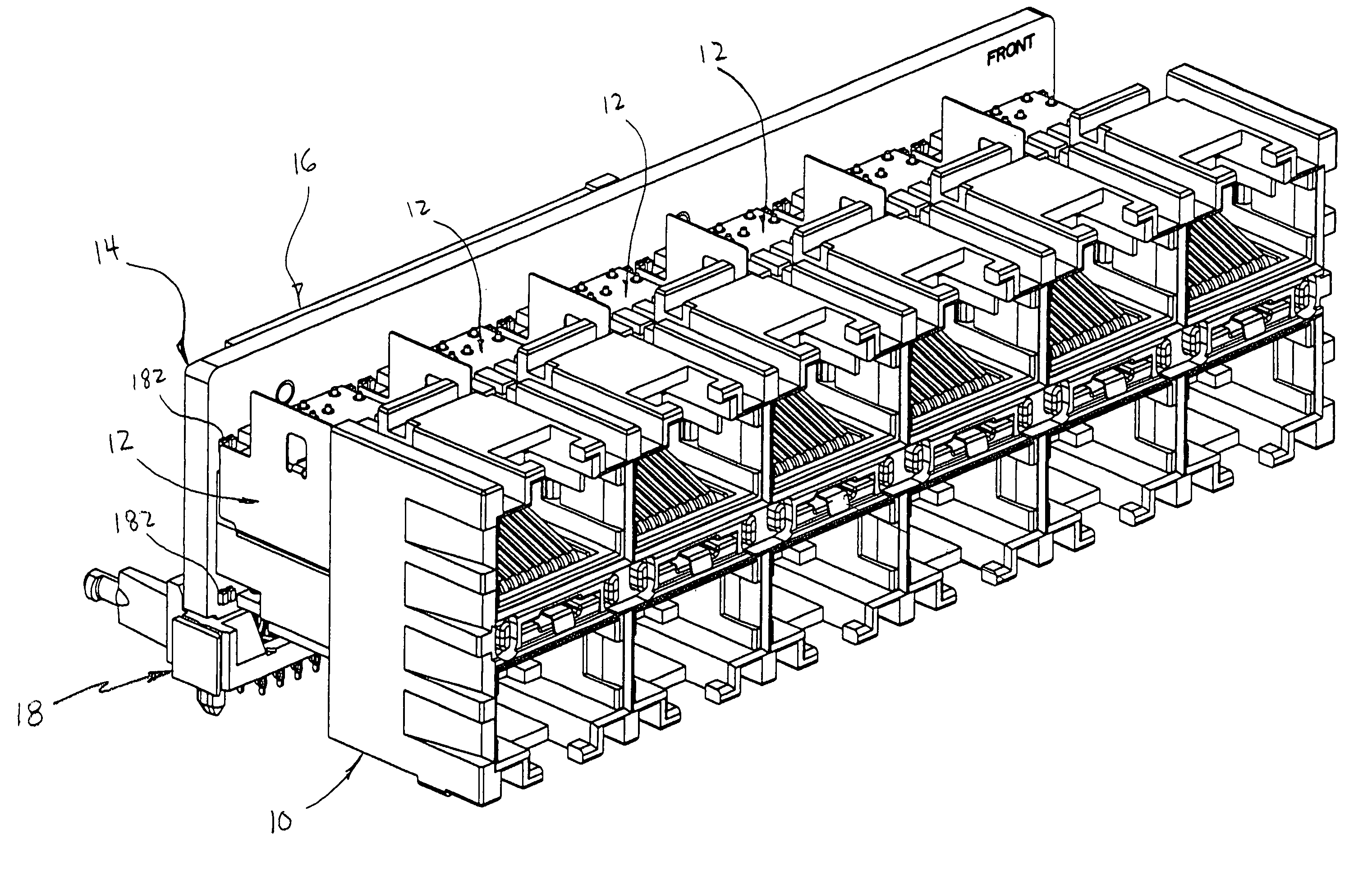
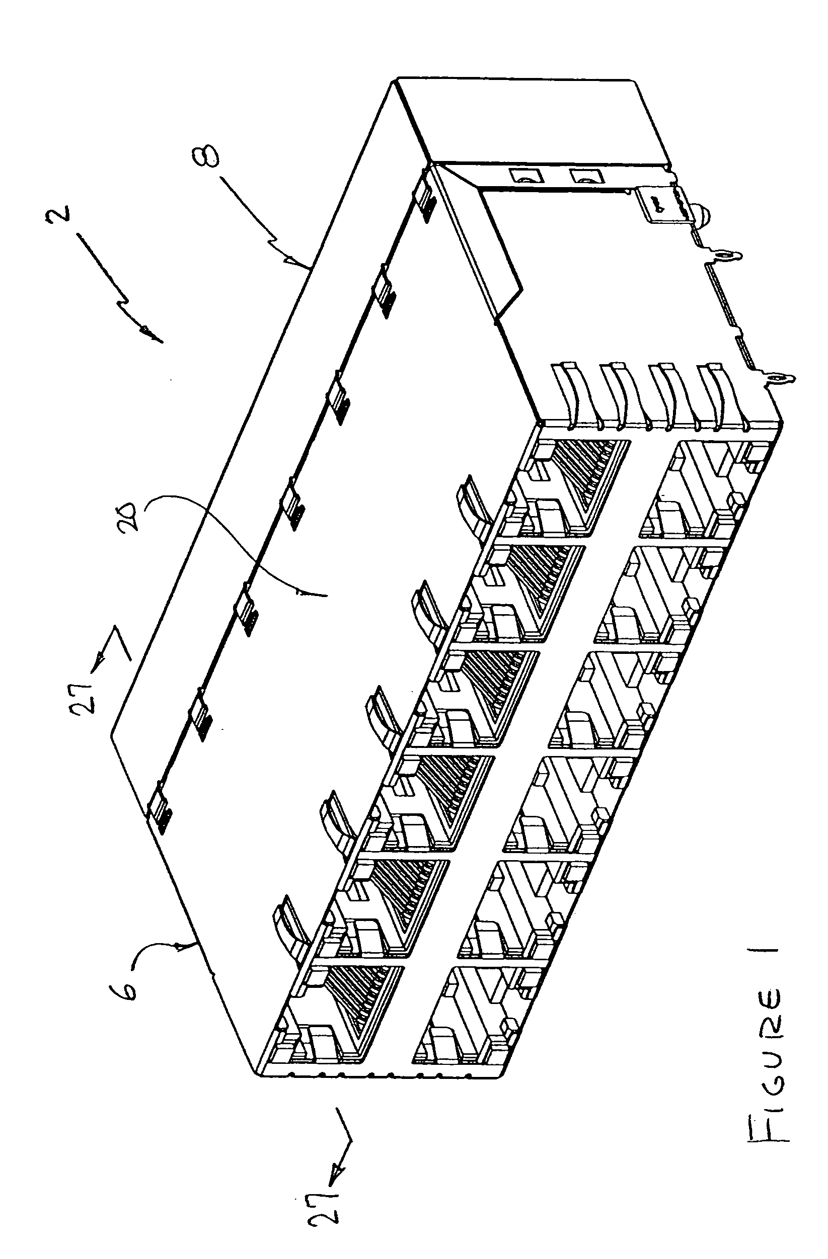
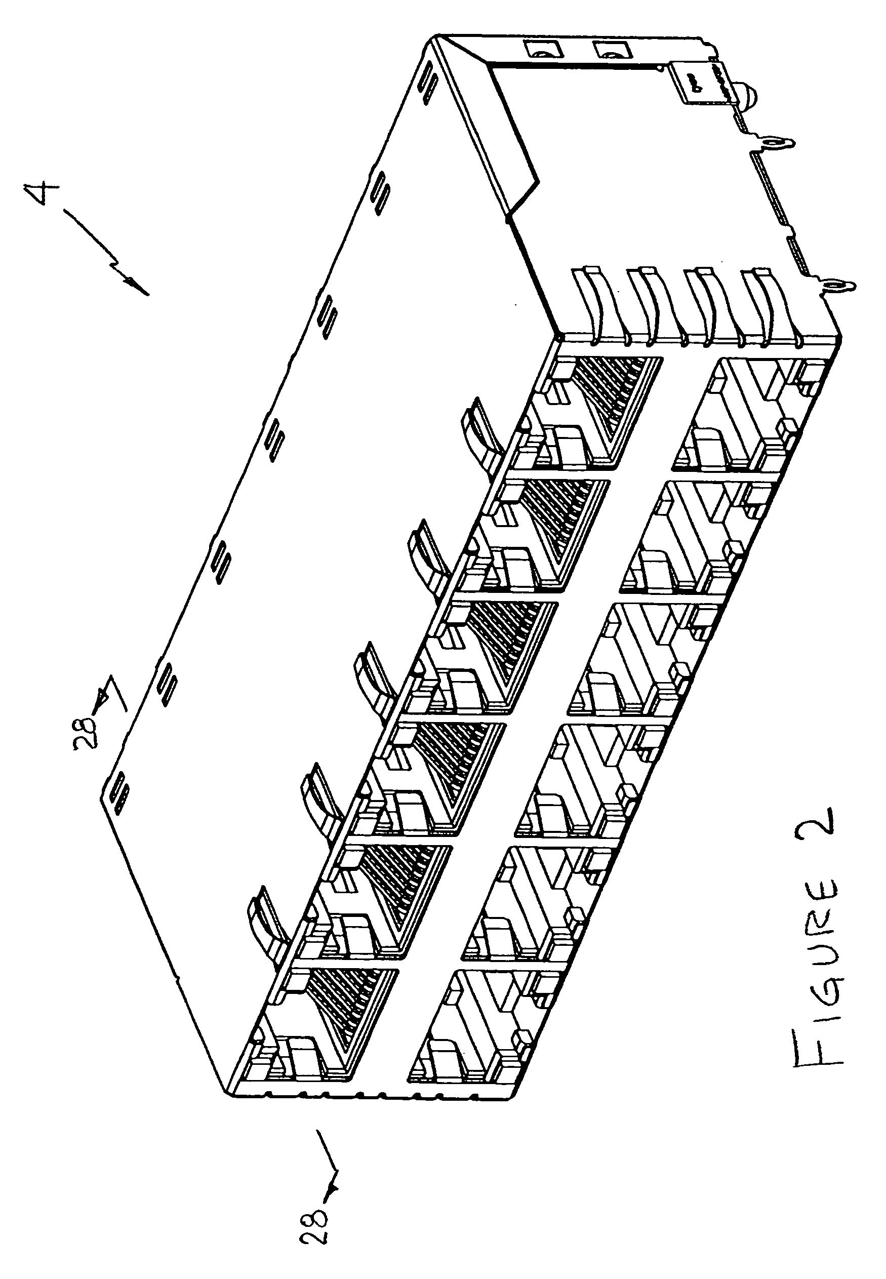
[0046] With reference first to FIGS. 1 and 2, the various components of the present invention will be described with respect to several possible embodiments, it being understood however that the shielding configuration of the present invention being applicable to any such exemplary device. As shown in FIG. 1, a multi-port or stacked jack configuration is shown generally at 2, where the connector 2 includes an integrated power over ethernet control card. As shown in FIG. 2, an electrical connector is shown at 4, where connector assembly 4 could take on one of two configurations. First, connector 4 could be an assembly where the power over ethernet control card is not integrated with the connector, but rather is positioned elsewhere on a motherboard and the power signals are routed through a control card on the motherboard, and thereafter to connector 4. Alternatively, connector 4 could be a configuration, where no power over ethernet is required, but is rather a stacked jack assembly...


PUM


Abstract

A stacked jack multi-port shielded and magnetically conditioned connector assembly is provided having a multi-port electrical connector housing having a plurality of housing ports adjacent a mating face thereof. A shield member comprises a base shield portion and sidewall portions extending from side edges of the base shield portion. The sidewall portions extend in opposite directions from the base shield portion. A plurality of modular connector subassemblies are adapted for stacking with the base shield portion positioned therebetween, and with one of the shield sidewall portions positioned against a side of one of the housings and the other shield sidewall portion is positioned against a side of the other housing.

Description

FIELD OF THE INVENTION [0001] The invention relates to a connection assembly providing multiple port connections, in a shielded stacked jack configuration. BACKGROUND OF THE INVENTION [0002] Known connector assemblies exist having multiple receptacle connectors in a common housing, which provide a compact arrangement of such receptacle connectors. Such a connector assembly is useful to provide multiple connection ports. Accordingly, such a connector assembly is referred to as a multi-port connector assembly. In preferred arrays, the housing has jacks one above the other, forming a plurality of arrays in stacked arrangement, so-called “stacked jack” arrangements. The receptacle connectors, that is, modular jacks, each have electrical terminals arranged in a terminal array, and have plug-receiving cavities. Specifically, the receptacle connectors are in the form of RJ-45 type modular jacks that establish mating connections with corresponding RJ-45 modular plugs. [0003] For example, as...

Claims


Application Information

Patent Timeline
IPC IPC(8): H01R13/66H01R24/00
CPCH01R24/64H01R13/6658
Inventor MURR, KEITH M.FOGG, MICHAEL W.CINA, MICHAEL F.
Owner TE CONNECTIVITY CORP
Why Eureka
Try Eureka