
AVAP: air valve and port for intravenous (IV) tubing

a technology of air valve and port, which is applied in the direction of intravenous devices, infusion devices, etc., can solve the problems of hindering the blood circulation, air embolism, and reducing so as to reduce the unproductive employment of healthcare practitioners, increase the productivity of intravenous drips, and reduce the effect of air embolism

Inactive Publication Date: 2005-12-22
LYDE FELICIA C +1
View PDF7 Cites 14 Cited by
  • Summary
  • Abstract
  • Description
  • Claims
  • Application Information

AI Technical Summary

Benefits of technology

[0008] This invention solves a healthcare safety issue, i.e., air embolism is a potentially lethal complication caused by preventable negligence. Air embolism is when air bubbles accumulate in the blood stream and hinder the circulation of blood. This invention prevents any air from entering a healthcare patient's blood stream and causing air embolism, also known as venous air embolism.
[0009] Use of this invention will lead to increased productivity of intravenous (IV) drips because the invention allows for a seamless interchange of medications and solutions. Moreover, use of the invention will decrease the unproductive employment of healthcare practitioners' skills and decrease the overburdening of healthcare practitioners' time. Therefore, use of this invention will lead to a more effective use of healthcare practitioners' time and talents and to the effective prevention of air embolism.
[0010] In accordance with these and other aspects of the invention, there is disclosed a valve for controlling the flow of fluid into a patient and preventing the introduction of air into the patient. The valve comprises a chamber comprising a bottom and a top base of the chamber. The top base is attached to the top of the chamber, has a top opening there through, and is adapted to facilitate the flow of the fluid through the top opening and the chamber. Further, a bottom base is attached to the bottom of the chamber and has a bottom opening disposed there through. A sphere is disposed within the chamber, whereby the sphere is adapted to float upon the fluid introduced, and is dimensioned and configured with respect to the bottom opening to prevent the discharge of air from the chamber and through the bottom opening when there is no fluid in the chamber and the sphere is disposed in its blocking position with respect to the bottom opening. Further, a stop mechanism is provided for preventing the sphere from blocking the top opening when the chamber is filled with the fluid. A mechanism is disposed adjacent the bottom opening to facilitate the withdrawal of air flowing through the chamber to enhance the amount of air that may be withdrawn from the chamber.
[0011] In a further aspect of this invention, a fluid valve is disclosed for preventing the flow of air into a patient. The valve comprises a chamber, which includes a top and a bottom. The top has a top opening introducing the fluid into the chamber and the bottom has a bottom opening for discharging the fluid from the chamber and into the patient. Further, a sphere is disposed in the chamber and adapted to rise and fall therein as the fluid is respectively introduced into or discharged from chamber, whereby the bottom opening is locked to prevent the discharge of air from the chamber and into the patient. A mechanism is provided to prevent the sphere from blocking the top opening and capturing air in the chamber when the chamber is filled with the fluid. The mechanism is disposed in a relatively close position to the upper door to enhance the free flow of fluid through the chamber.

Problems solved by technology

Air embolism is when air bubbles accumulate in the blood stream and hinder the circulation of blood.
Moreover, use of the invention will decrease the unproductive employment of healthcare practitioners' skills and decrease the overburdening of healthcare practitioners' time.

Method used


Image

  • AVAP: air valve and port for intravenous (IV) tubing
  • AVAP: air valve and port for intravenous (IV) tubing
  • AVAP: air valve and port for intravenous (IV) tubing

Examples


Embodiment Construction

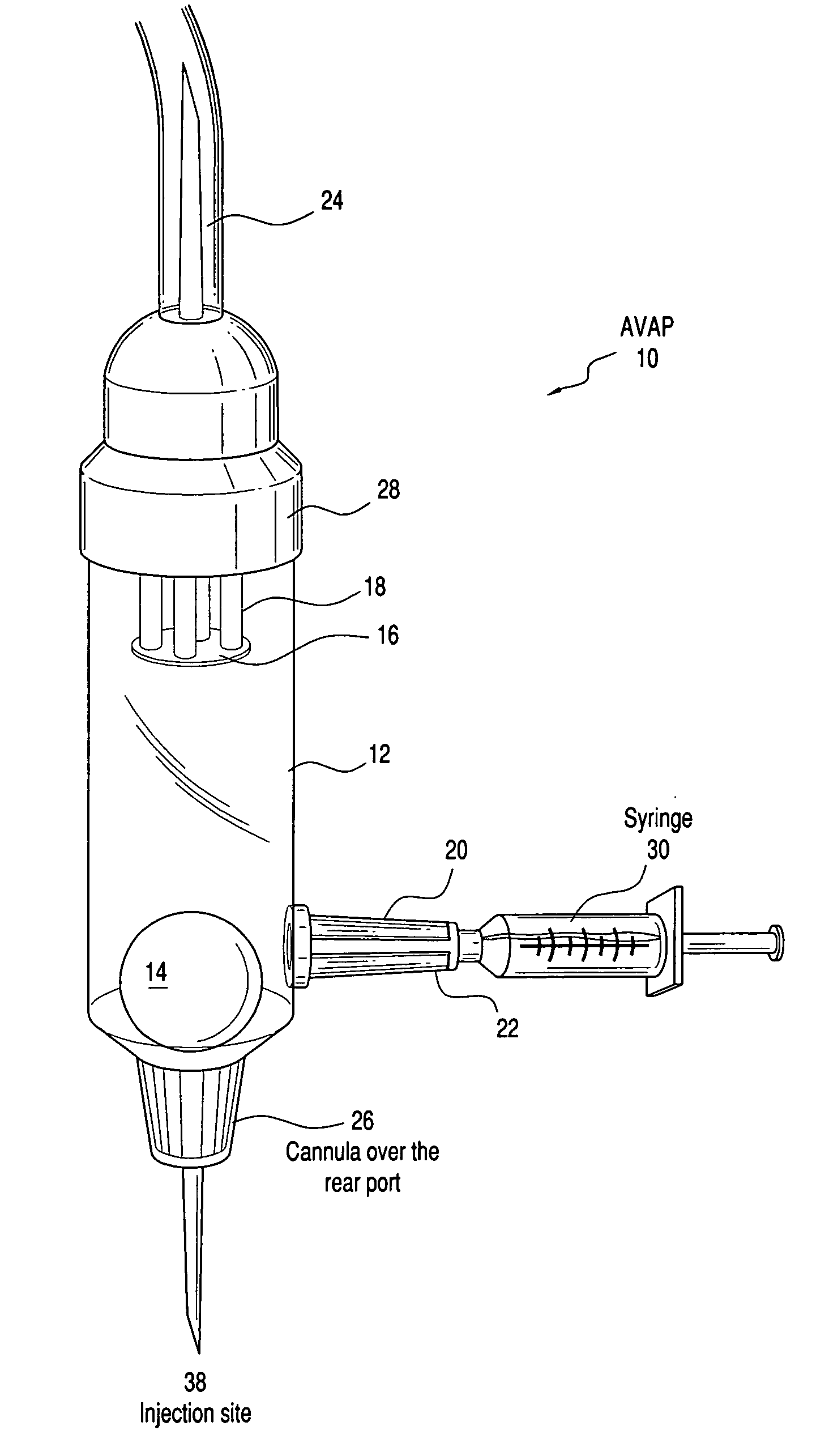
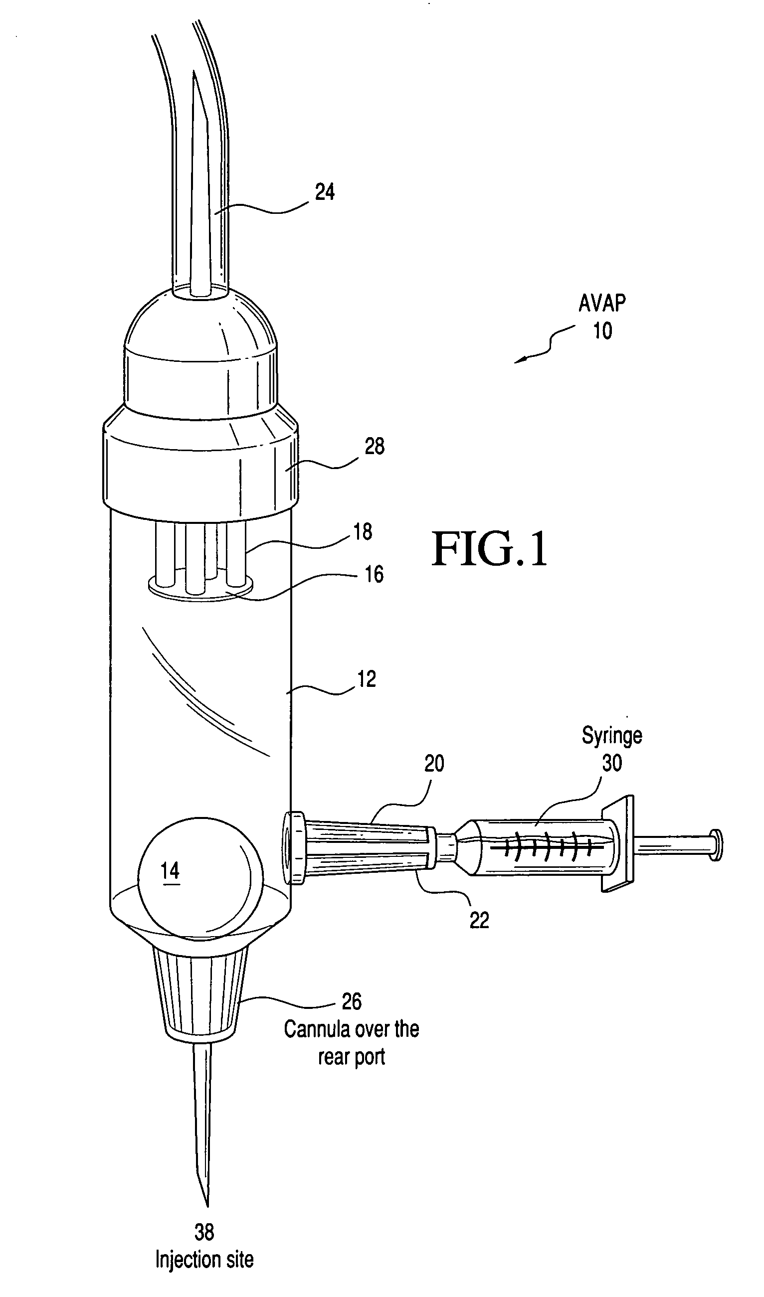
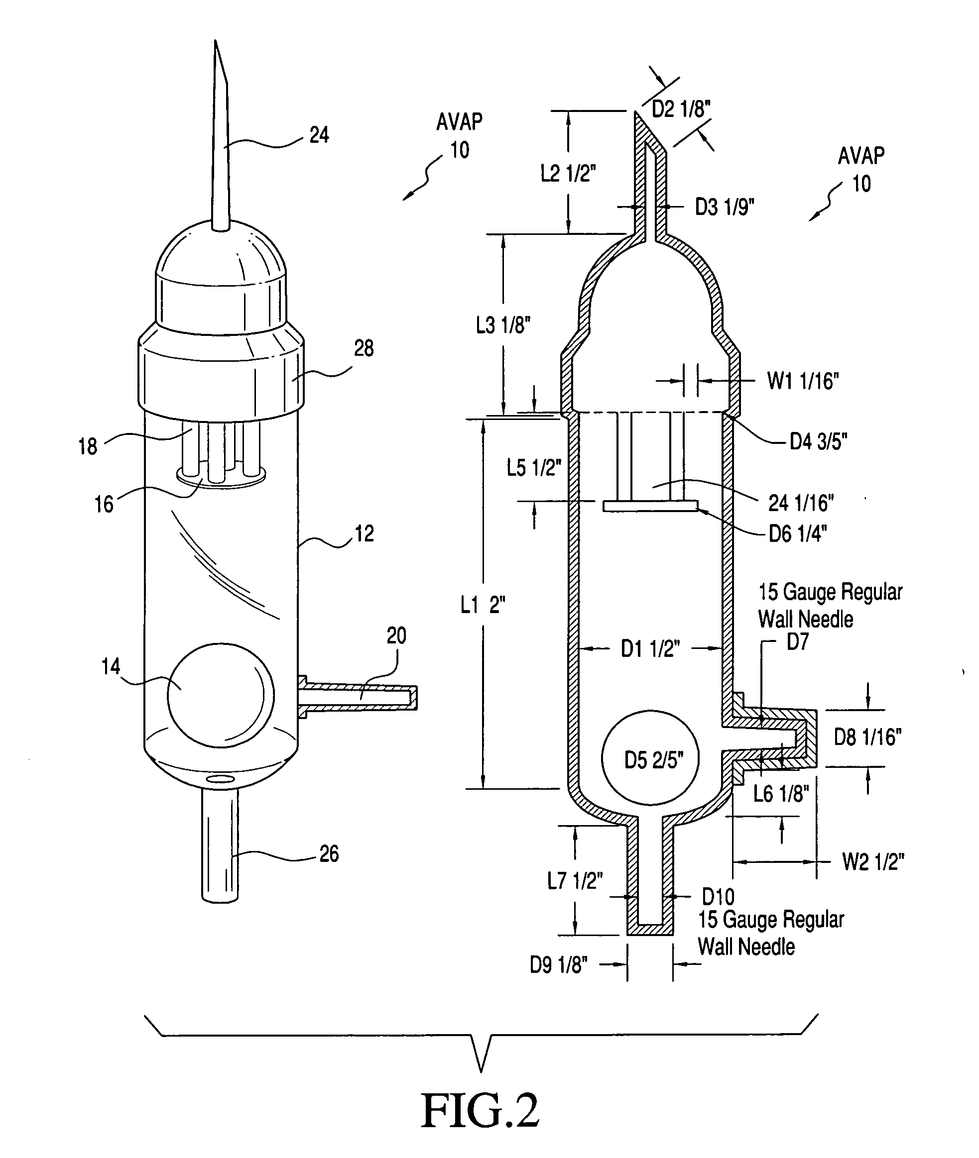
[0017] Referring now to the drawings and in particular to FIG. 1, there is shown an illustrative embodiment of an air valve 10, which may be used to extract air from intravenous (IV) tubing and prevent any air from being introduced into a patient's veins. Air valve 10 comprises a universal cylindrical drip chamber 12 with a free-floating sphere 14 inside, a horizontal circular ring 16 attached to four posts 18 that extend from the top of the inside of the drip chamber, and an external port 20 with a removable cap-cover 22 at the base of valve 10. As will be explained, the ring 16 and posts 18 form a stop mechanism to prevent the sphere 14 from blocking. The air valve 10 also comprises a spike 24 at the top of the cylindrical drip chamber 12, having a top base 28, and a bottom base 26 at the bottom of the cylindrical drip chamber 12.

[0018] In an illustrative embodiment, all parts of the valve may be made by any of the following plastic polymers: polyethylene; (non-DEHP) PVC; or (non...


PUM


Abstract

The invention provides an air valve for use in getting air out of intravenous (IV) tubing and preventing the air from intravenous (IV) tubing from entering healthcare patients' veins. In an illustrative embodiment the air valve is attached at one end to the intravenous (IV) tubing that hangs from an intravenous (IV) bag and at the other end to the injection site, where a needle is inserted into a patient's vein. The invention prevents any air from entering a healthcare patient's blood stream and causing air embolism, a potentially lethal complication caused by an accumulation of air bubbles in the blood stream that hinders the circulation of blood. The invention will also lead to increased productivity of intravenous (IV) drips since it allows for a seamless interchange of medications and solutions.

Description

BACKGROUND OF THE INVENTION [0001] There is no prior technology for getting air out of intravenous (IV) tubing and preventing the air from intravenous (IV) tubing from entering healthcare patients' veins. Presently, healthcare practitioners tap intravenous (IV) tubing with their fingernails to prime new intravenous (IV) tubing and to push air out of the intravenous (IV) tubing. If healthcare practitioners cannot get the air out of the intravenous (IV) tubing, then they must prime new intravenous (IV) tubing; however, this leads to unnecessary multiple injections to healthcare patients' veins. [0002] According to Dr. John Peter Gruen of the Department of Neurosurgery at the University of Southern California, air embolism is “the entry of air into the blood stream with formation of bubbles that can reach sufficient volume that they interfere with normal pumping of blood by the heart.” Moreover, according to Dr. T. Kapoor and Dr. G. Gutierrez of the Department of Internal Medicine at G...

Claims


Application Information

Patent Timeline
IPC IPC(8): A61M5/00A61M5/40
CPCA61M5/40
Inventor LYDE, FELICIA C.GILLS, CASSANDRA ANN
Owner LYDE FELICIA C
Learn More