Lightweight concrete composite wall panels

Inactive Publication Date: 2005-12-29
AMAZON FORMS ONE
View PDF8 Cites 21 Cited by
  • Summary
  • Abstract
  • Description
  • Claims
  • Application Information

AI Technical Summary

Benefits of technology

[0012] The frame may be configured to receive therein a window frame or a door frame. The frame accordingly includes a header, a first side, and a second side. The frame may further include a footer. The header, the first side, and the second side e

Problems solved by technology

Wood unfortunately has become extremely expensive due to reduced supplies caused by restrictions resulting from today's environmentally conscious society.
Further, wood often does not provide the structural

Method used


Image

  • Lightweight concrete composite wall panels
  • Lightweight concrete composite wall panels
  • Lightweight concrete composite wall panels

Examples


Example

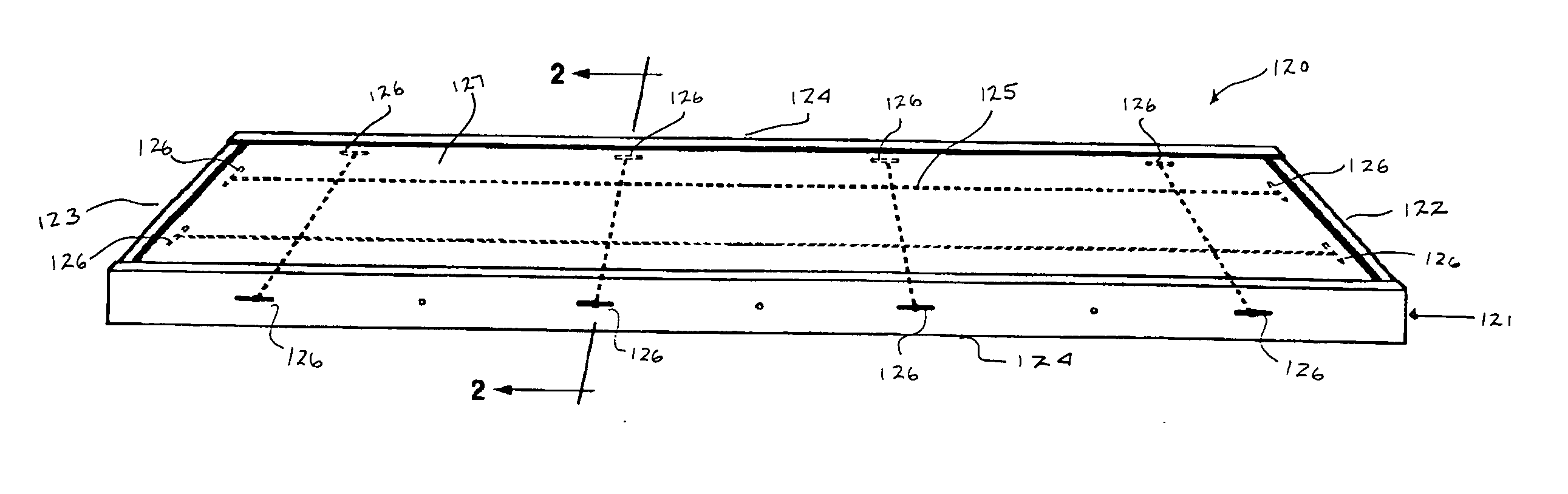
[0034] The foregoing invention is a unitary lightweight concrete composite wall panel. The wall panel may be used in the construction of either interior or exterior walls. A wall panel may be configured as a load bearing or non-load bearing wall. The size of a wall panel ranges from an individual wall panel forming a portion of a wall to a wall panel spanning an entire wall length thereby furnishing a single complete wall.

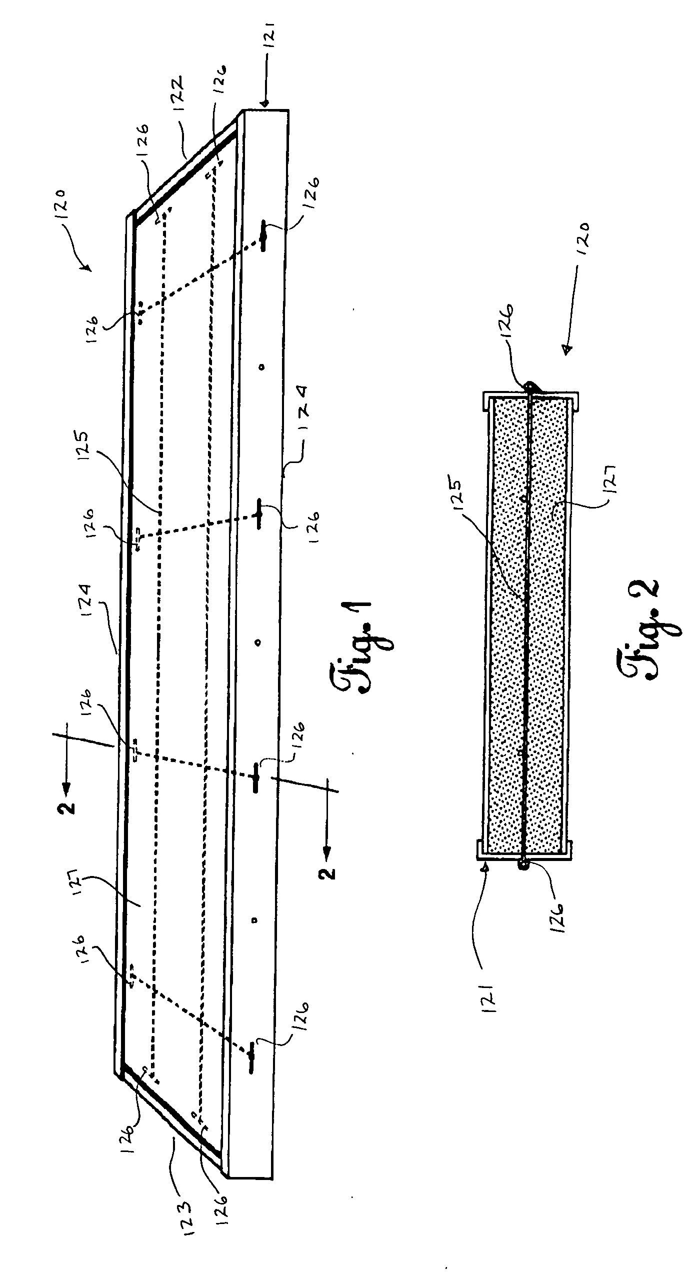
[0035] As illustrated in FIGS. 1 and 2, a unitary lightweight concrete composite wall panel 120 according to a first embodiment includes a frame 121 filled with a lightweight concrete composite 127 such as that disclosed in U.S. patent application Ser. Nos. 09 / 887,369 and 10 / 374,886, the disclosures of which are herein incorporated by reference. The frame 121 includes a top end 122, a bottom end 123, and two sides 124. The frame 121 may be constructed from any suitable material such as metal or aluminum as one continuous member or as individual members secured tog...


PUM


Abstract

Unitary lightweight concrete composite wall panels include a frame filled with lightweight composite concrete. The wall panels may be used in the construction of either interior or exterior walls, and a wall panel may be configured as a load bearing or non load bearing. The size of a wall panel ranges from an individual wall panel forming a portion of a wall to a wall panel spanning an entire wall length, thereby furnishing a single complete wall. A wall panel may further be configured to support either a window or door.

Description

CROSS-REFERENCE TO RELATED APPLICATIONS [0001] This application is a continuation-in-part of application Ser. No. 10 / 374,886, filed Feb. 26, 2003, which was a continuation-in-part of U.S. Pat. No. 6,827,570 B2, issued Dec. 7, 2004. [0002] This present application claims all available benefit, under 35 U.S.C. § 119(e), of U.S. provisional patent application Ser. No. 60 / 604,947, filed Aug. 27, 2004. By this reference, the full disclosure of U.S. provisional patent application Ser. No. 60 / 604,947 is incorporated herein as though now set forth in its entirety.BACKGROUND OF THE INVENTION [0003] 1. Field of the Invention [0004] The present invention relates to lightweight concrete and, more particularly, but not by way of limitation, to unitary lightweight concrete composite wall panels. [0005] 2. Description of the Related Art [0006] The primary building materials utilized today are wood and concrete. Wood unfortunately has become extremely expensive due to reduced supplies caused by res...

Claims


Application Information

Patent Timeline
IPC IPC(8): E04C2/00E04C2/04E04C2/38
CPCE04C2/384E04C2/044
Inventor SUMRALL, ORBIN F.
Owner AMAZON FORMS ONE
Why Eureka
Try Eureka