Electrode shapes and positions for reducing loss of contact in an implantable ECG recorder

Inactive Publication Date: 2012-05-03
MEDTRONIC INC
View PDF9 Cites 14 Cited by
  • Summary
  • Abstract
  • Description
  • Claims
  • Application Information

AI Technical Summary

Benefits of technology

[0007]A second embodiment accomplishes a similar result by placing the electrodes on the ends of the outward facing halves of the device, covering part of the edge and/or end surfaces of the device while maintaining a distance from the back-side of the device in order to reduce susceptibility from motion artifacts due to the movement of the underlying tissue, such as the muscle fascia in some implants. Generally these devices will have curved end and/or side surfaces comfort, so that the electrodes are correspondingly curved, maximizing surface area.
[0008]A third embodiment employs electrodes which covers end portions of the device including both the inward and outward facing surfaces, which has the added bene

Problems solved by technology

These bubbles may in some cases cover one or both electrodes, interfering with sensing of the ECG signal.
As implantable monitors

Method used


Image

  • Electrode shapes and positions for reducing loss of contact in an implantable ECG recorder
  • Electrode shapes and positions for reducing loss of contact in an implantable ECG recorder
  • Electrode shapes and positions for reducing loss of contact in an implantable ECG recorder

Examples


Embodiment Construction

[0014]The following detailed description is exemplary in nature and is not intended to limit the scope, applicability, or configuration of the invention in any way. Rather, the following description provides practical illustrations for implementing exemplary embodiments of the present invention.

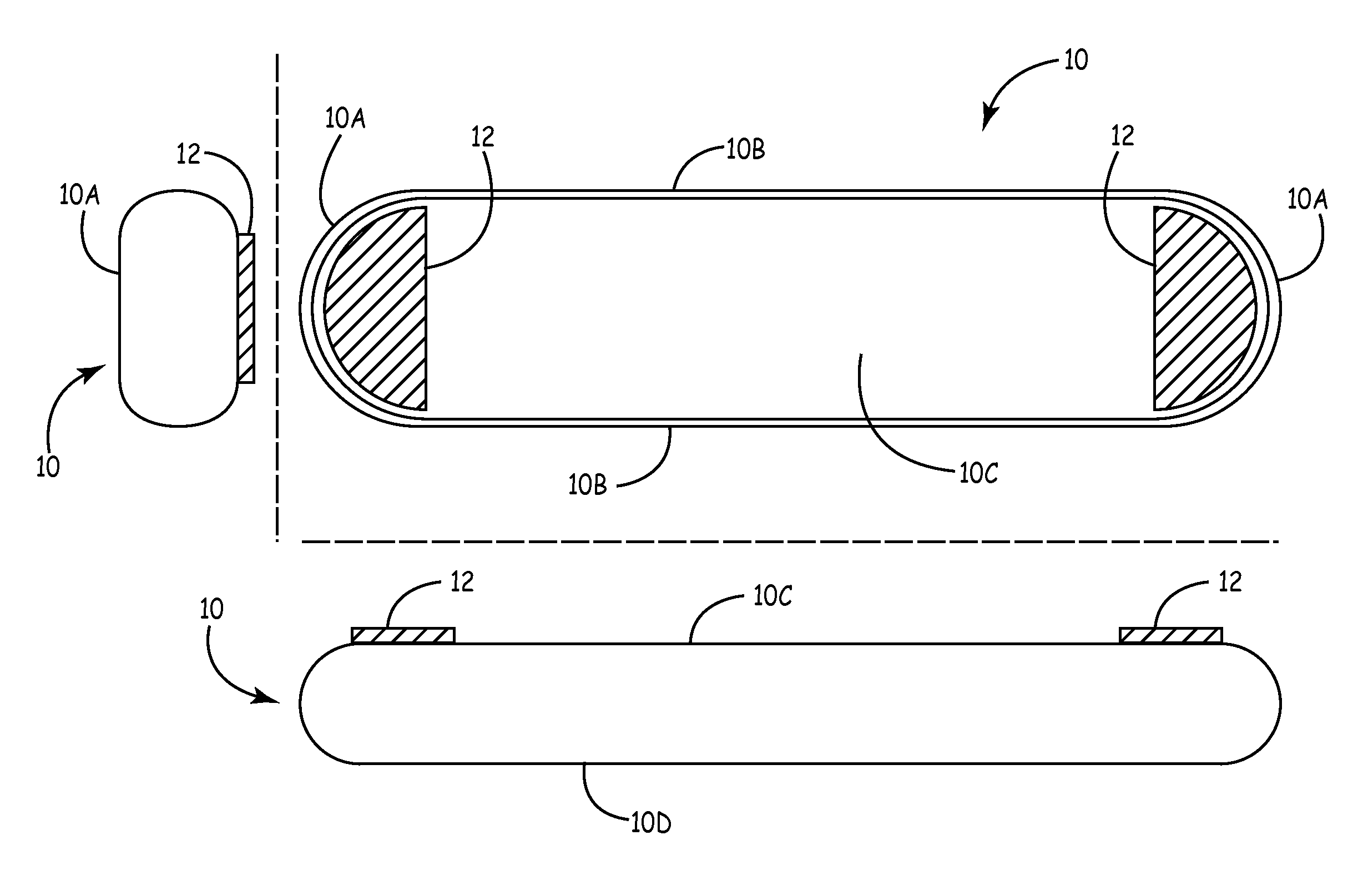
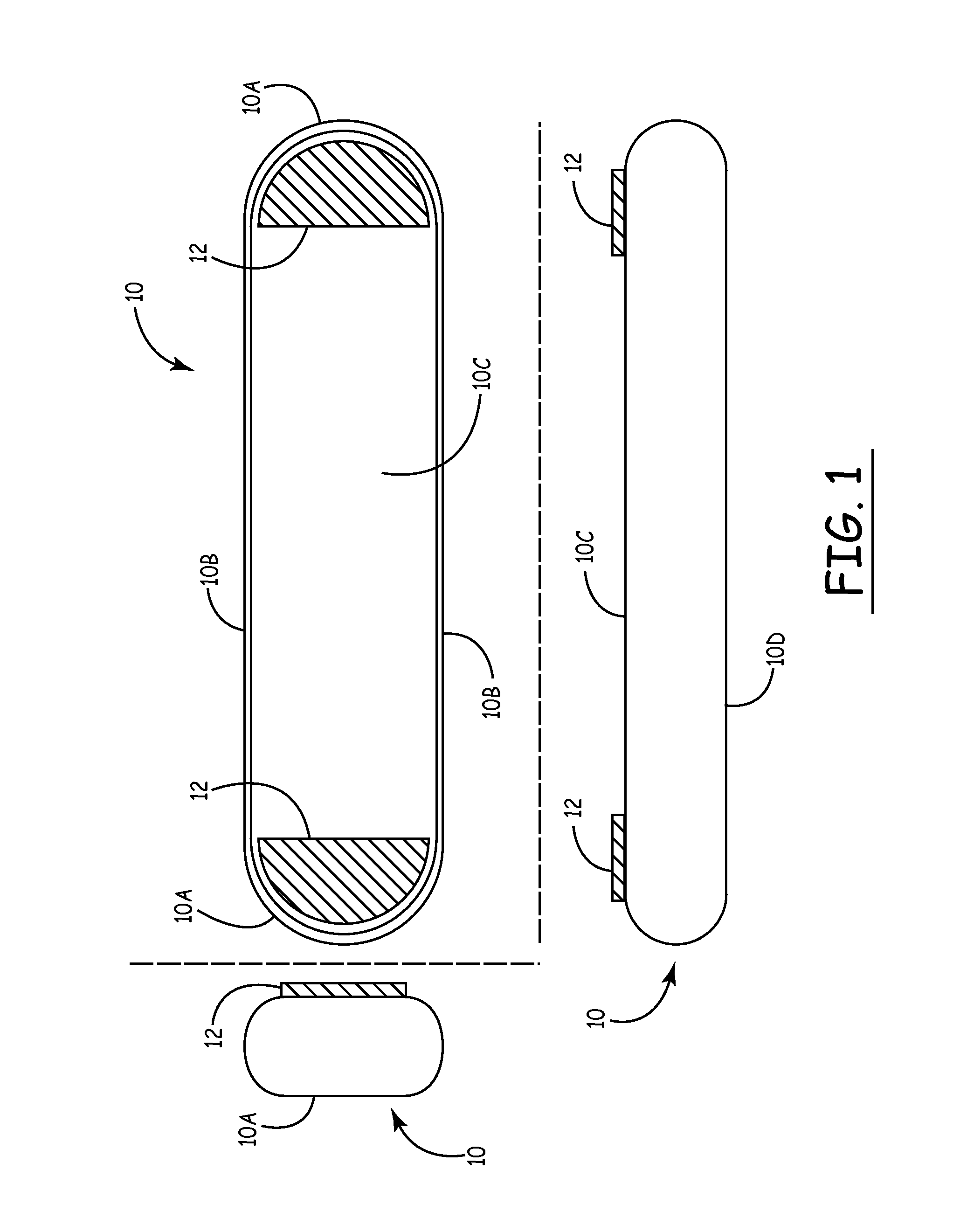
[0015]FIG. 1 is a representation of an implantable medical device (IMD) 10 that may be used in accordance with certain embodiments of the invention. The device may be any device that is capable of measuring hemodynamic parameters (e.g., blood pressure signals) from within a ventricle of a patient's heart, and which may further be capable of measuring other signals, such as the patient's electrogram (EGM).

[0016]The internal circuitry and other functional components of the device may correspond generally to those described in the above-cited Klein, et al, Bennett, et al. and / or Lee patents, incorporated herein by reference. The circuitry typically includes circuitry for monitoring ECG signals, ...


PUM


Abstract

An improved design for subcutaneous monitors that addresses the problem caused by bubbles of air may remain in the pocket in which the device is implanted. As implantable monitors and their associated electrodes are reduced in size, these bubbles may in some cases cover one or both electrodes, interfering with sensing of the ECG signal. The invention addresses this problem by configuring the electrodes to increase the pressure of the electrodes against the tissue above the electrodes relative to the pressures exerted by the adjacent outer facing surfaces of the device.

Description

CROSS-REFERENCE TO RELATED APPLICATIONS[0001]This application claims the benefit of U.S. Provisional Application No. 61 / 407,204, filed on Oct. 27, 2010. The disclosure of the above application is incorporated herein by reference in its entirety.BACKGROUND[0002]This invention relates to an implantable monitoring device for sensing physiologic events with minimally invasive intrusion into an animal or patient body, and is particularly well suited for long term monitoring of body events like ElectroCardioGrams (ECG's) and in monitoring other body physiologic events. By enabling easy monitoring and recording of physiologic events in the patient's body, such events can then be studied at leisure outside the body, providing research, diagnostic and therapeutic opportunities not otherwise available.[0003]Some currently available implantable subcutaneous ECG recording systems employ ECG electrodes located on an outward-facing, generally flat surface area of the device. The electrodes are so...

Claims


Application Information

Patent Timeline
IPC IPC(8): A61B5/042
CPCA61B5/0006A61B5/0422A61B5/076A61B5/6861A61B2560/0406A61B2562/0209A61B5/287
Inventor GORDON, CHARLES R.LEE, BRIAN B.BARROR, MICHAEL W.
Owner MEDTRONIC INC
Why Eureka
Try Eureka