Filter cross brace

a cross brace and filter technology, applied in the direction of filtration separation, colloidal chemistry, separation processes, etc., can solve the problems of complex manufacturing of framed filters, inherently complicated assembly to manufacture, and difficult automation production process implementation of framed filters

Inactive Publication Date: 2005-12-29
3M INNOVATIVE PROPERTIES CO
View PDF21 Cites 69 Cited by
  • Summary
  • Abstract
  • Description
  • Claims
  • Application Information

AI Technical Summary

Benefits of technology

[0006] The invention is related to a framed filter media comprising a pleated filter media having a fluid inlet face and a fluid outlet face with peripheral sidewalls. The peripheral sidewalls of the pleated filter are attached to the frame generally by an adhesive. The frame is preferably a flexible strip frame formed into three or more (up to an infinite number if the sidewall sections(s) is formed into a circular filter frame) sidewall sections each having a substantially flat sidewall and at least two projecting filter retaining tabs which form a flange on a first face of the sidewall section for containing the filter along its peripheral sidewalls and any adhesive. A cross brace fits into at least one pleat of the framed pleated filter m

Problems solved by technology

This type of approach permits more flexibility in terms of frame forms and functionality than unitary filter frames, however, it generally results in a framed filters which are complicated to manufacture.
This type of framed filter would be very difficult to implement in an automated production process due to the strategic placement of the adhesive within an enclosed space and the need for rapid assembly of three three-dimension pieces coming together simultaneously with very c

Method used


Image

  • Filter cross brace
  • Filter cross brace
  • Filter cross brace

Examples


Embodiment Construction

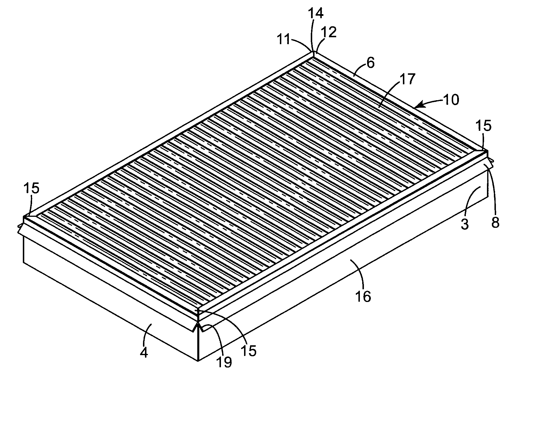
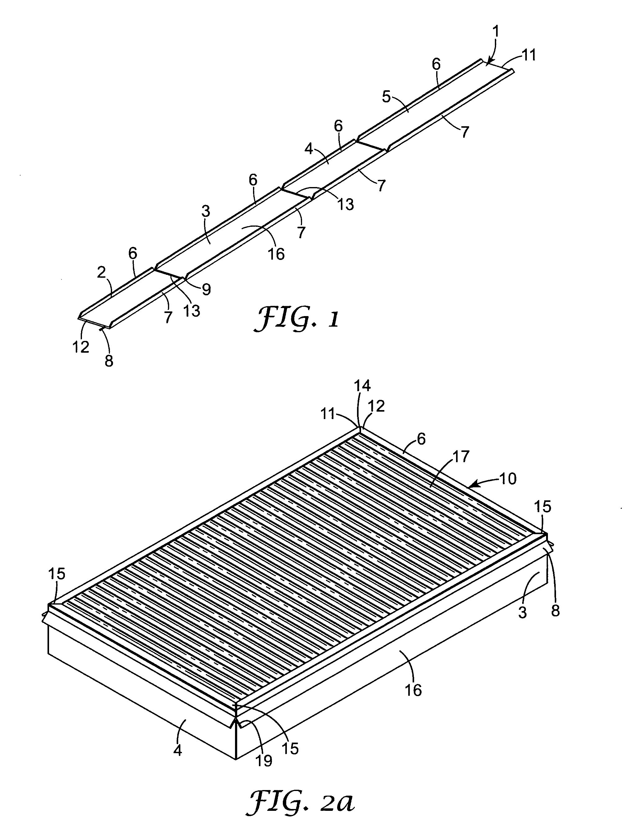
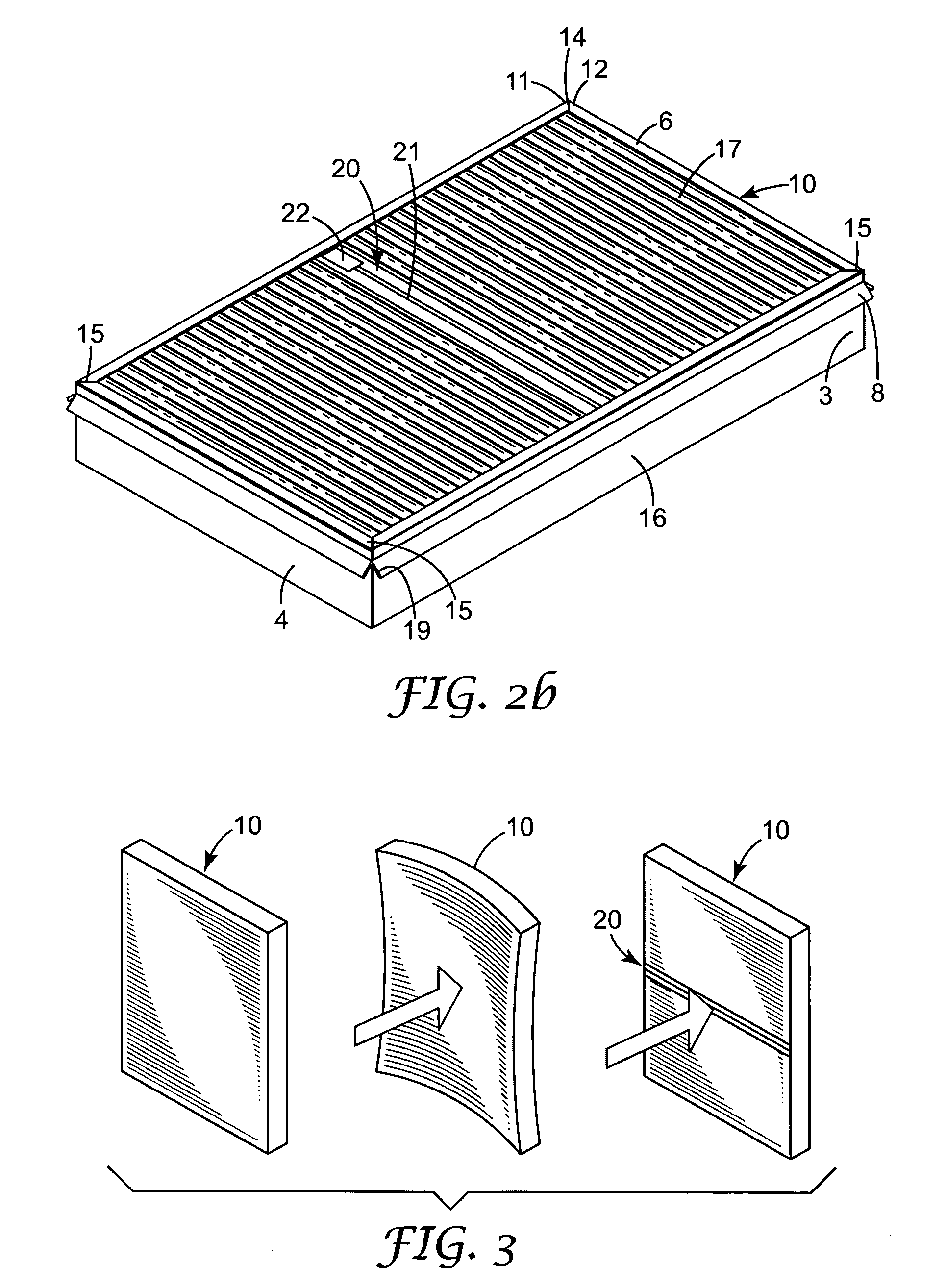
[0022] The framed filter media comprises a pleated filter media having a fluid inlet face and a fluid outlet face with peripheral sidewalls attached to a flexible frame formed into three or more (up to an infinite number if the sidewall sections(s) is formed into a circular filter frame) sidewall sections. The sidewall sections generally have a substantially flat sidewall and at least one projecting filter retaining tab, preferably two, which form a flange on a first face of the sidewall section for containing the filter sidewalls and any adhesive. The flange, or one or both tabs, also contains a cross brace which fits into at least one pleat of the framed pleated filter media. The cross brace fits into the space formed by the pleated filter media but generally is not in continuous contact with the filter media forming the pleat. The cross brace can be flexible to allow it to bend for insertion into the pleat but is rigid under compression. The cross brace has end keys for insertion...


PUM

PropertyMeasurementUnit
Fractionaaaaaaaaaa
Fractionaaaaaaaaaa
Angleaaaaaaaaaa

Abstract

The invention is related to a framed filter media comprising a pleated filter media having a fluid inlet face and a fluid outlet face with peripheral sidewalls. The peripheral sidewalls of the pleated filter are attached to the frame generally by an adhesive. The frame is preferably a flexible strip frame formed into three or more (up to an infinite number if the sidewall sections(s) is formed into a circular filter frame) sidewall sections each having a substantially flat sidewall and at least two projecting filter retaining tabs which form a flange on a first face of the sidewall section for containing the filter along its peripheral sidewalls and any adhesive. A cross brace is also inserted within the filter retaining tabs which fits into at least one pleat of the framed pleated filter media. The cross brace fits into the space formed by the pleated filter media but is not in continuous contact with the filter media forming the pleat. The cross brace can be flexible and has end keys or projections for insertion into the filter frame flanges and attachment to the sidewall sections and/or the flange. In a particular embodiment, the cross brace has a continuous non-linear profile with an internal profiled groove with a mating surface, for insertion and locking of removable end keys or other items, such as handles and labels, which removable items have a profile that mates with, or locks the mating surface of the profiled groove.

Description

BACKGROUND OF THE INVENTION [0001] This invention is directed at a unitary framed filter where the filters form is capable of being formed by a continuous extrusion process. [0002] Conventionally three dimensional filter frames are formed by injection molding or similar type processes. In its simplest variation, the frame is directly formed as a unitary structure. A simple technique for this is described in U.S. Pat. No. 2,032,262 where a pleated filter is held in a jig with only the edge portions extending out of the jig. This jig is then inserted into a mold form and a plastic type material is injected, embedding the exposed pleat edges in the space between the jig and the mold form. Similarly, U.S. Pat. No. 5,792,229 shows an elastomeric filter frame formed directly on a pleated filter media by injection molding a foaming resin into the pleats of the pleated filter along the periphery of the pleated filter in one embodiment of the invention described. This filter requires a separ...

Claims


Application Information

Patent Timeline
IPC IPC(8): B01D46/00B01D46/10B01D46/42B01D46/52
CPCB01D46/0001B01D46/0002B01D46/0005B01D46/10Y10S55/31B01D46/4227B01D46/521B01D2265/06B01D2271/027B01D46/42
Inventor DUFFY, DEAN R.
Owner 3M INNOVATIVE PROPERTIES CO
Why Eureka
Try Eureka