Self-contained viscous liquid dispenser with a foaming pump

a dispenser and foaming technology, applied in the field of viscous liquid dispensers, can solve the problems of not being widely used or incorporated into the foaming pump mechanism

Inactive Publication Date: 2005-12-29
KIMBERLY-CLARK WORLDWIDE INC
View PDF8 Cites 39 Cited by
  • Summary
  • Abstract
  • Description
  • Claims
  • Application Information

AI Technical Summary

Benefits of technology

[0016] The dispenser may also include a mounting mechanism that may be configured as an integral component of the housing. The mounting mechanism allows the dispenser to be detachably connected to complimentary mounting structure on a wall

Problems solved by technology

For various reasons, however, such foaming pump mechanisms have not been widely used or incorporated w

Method used


Image

  • Self-contained viscous liquid dispenser with a foaming pump
  • Self-contained viscous liquid dispenser with a foaming pump
  • Self-contained viscous liquid dispenser with a foaming pump

Examples


Embodiment Construction

[0026] Reference will now be made in detail to embodiments of the invention, one or more examples of which are illustrated in the drawings. Each example is provided by way of explanation of the invention, and not meant as a limitation of the invention. For example, features illustrated or described as part of one embodiment, may be used with another embodiment, to yield still a further embodiment. It is intended that the present invention include modifications and variations to the embodiments described herein.

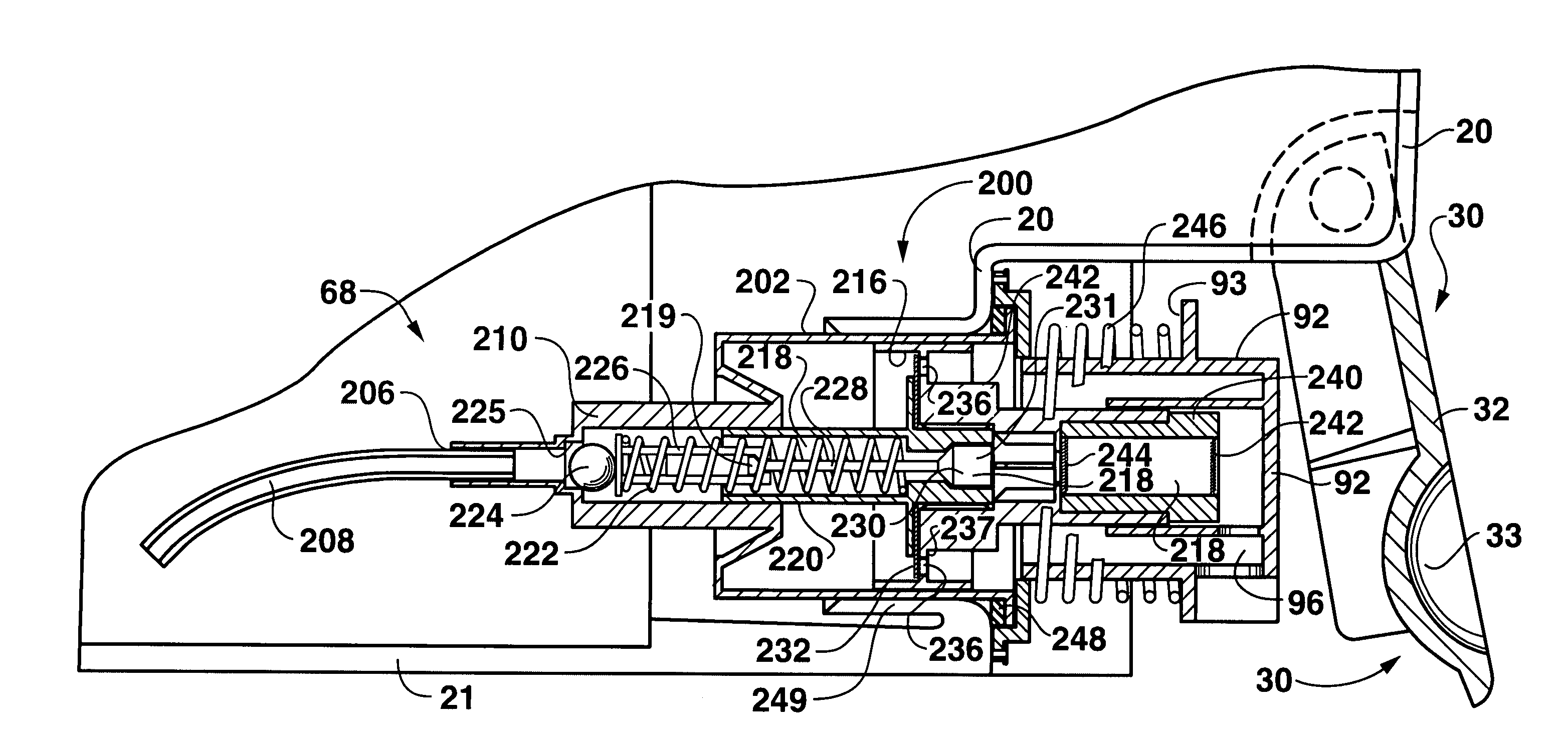
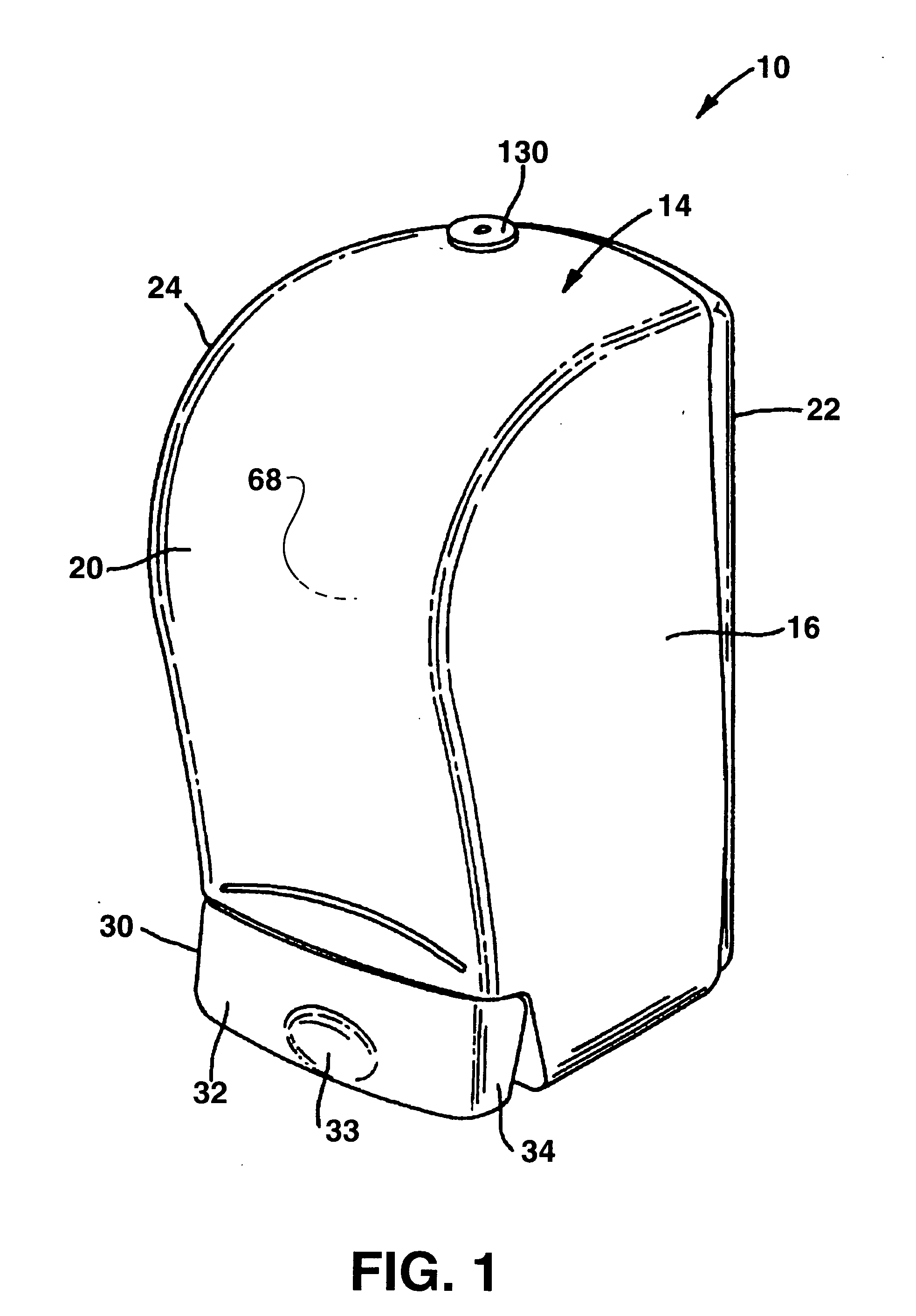
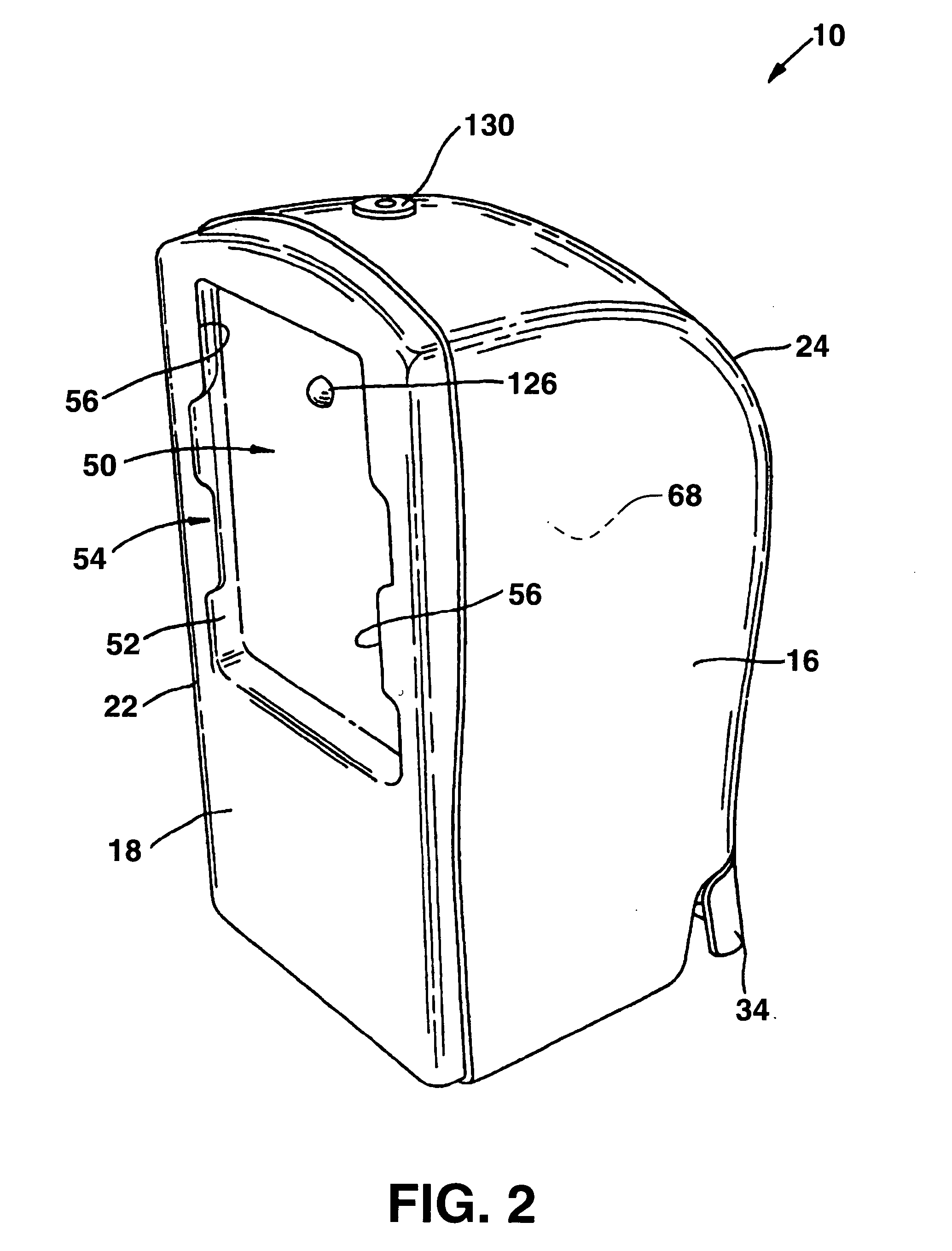
[0027] A viscous liquid dispenser 10 with a foaming pump mechanism 200 according to the invention is illustrated generally in the figures. The dispenser 10 is illustrated and described herein as a liquid soap dispenser, which is a particularly useful embodiment of the present invention. However, it should be appreciated that the present invention is not limited to a dispenser for liquid soap, but has application in any environment wherein it is desired to dispense a metered a...


PUM


Abstract

A self contained viscous liquid dispenser with a foaming pump mechanism includes a housing defining an internal liquid reservoir. A foaming pump mechanism is configured with the housing and includes a horizontally disposed pump chamber fitted through an opening in the housing to extend into the reservoir. A pump cylinder is slidably disposed and retained in the chamber. Actuation of the pump cylinder results in a liquid/air mixture within the pump chamber being pressurized and dispensed from the chamber as a foam.

Description

FIELD OF THE INVENTION [0001] The present invention relates to the field of viscous liquid dispensers, for example soap dispensers, and particularly to a viscous liquid dispenser having a foaming pump mechanism. BACKGROUND OF THE INVENTION [0002] Various configurations and models of liquid dispensers, particularly liquid soap dispensers, are well known in the art. Conventional dispensers employed in public restrooms and the like are wall mounted units that typically include a house or structure that is permanently affixed to a wall. These dispensers usually include an access door or member so that the dispenser can be opened by a maintenance person for refilling or servicing. With certain types of dispensers, separate refill cartridges are inserted into the housing structure. With other types of dispensers, the maintenance technician must directly refill a reservoir provided in the housing structure. The dispensers typically include a delivery device, such as a dosing pump, and a de...

Claims


Application Information

Patent Timeline
IPC IPC(8): A47K5/14B05B7/00B67D7/78B05B11/00
CPCB05B11/3087B05B7/0037B05B11/1087
Inventor LEWIS, RICHARD P.SHOAF, VICTOR S.MAHAFFEY, CLEARY E.
Owner KIMBERLY-CLARK WORLDWIDE INC
Why Eureka
Try Eureka