Controller of ejector mechanism in injection molding machine and method of setting terminal position of forward motion of ejector pins of ejector mechanism

a technology of ejector mechanism and controller, which is applied in the direction of manufacturing tools, coatings, applications, etc., can solve problems such as brake device malfunction, and achieve the effect of reducing the cause of brake device malfunction and preventing excessive wear

Inactive Publication Date: 2005-12-29
FANUC LTD
View PDF6 Cites 2 Cited by
  • Summary
  • Abstract
  • Description
  • Claims
  • Application Information

AI Technical Summary

Benefits of technology

[0012] According to the present invention, the terminal position of the forward motion of the ejector pins is set to an appropriate position where the return springs generate the elas

Problems solved by technology

If the elastic force of the springs is greater than the retaining force of the brake device in a state where the ejector pins are retained at the terminal position, fricti

Method used


Image

  • Controller of ejector mechanism in injection molding machine and method of setting terminal position of forward motion of ejector pins of ejector mechanism
  • Controller of ejector mechanism in injection molding machine and method of setting terminal position of forward motion of ejector pins of ejector mechanism
  • Controller of ejector mechanism in injection molding machine and method of setting terminal position of forward motion of ejector pins of ejector mechanism

Examples


first embodiment

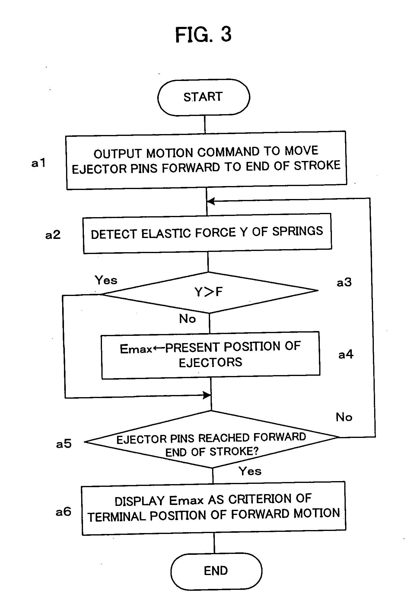
[0029]FIG. 3 shows processing to be performed by the CNC CPU 27 for setting the terminal position of the forward motion of the ejector pins according to the present invention.

[0030] In a state where there is no molded product in a mold, e.g. immediately after attaching a mold to an injection molding machine, and thus the ejector pins 3 come in contact with no molded product in a forward motion, when a command to determine a criterial position is inputted from the display / MDI device 29, the CNC CPU 27 performs the processing of algorism as shown in FIG. 3.

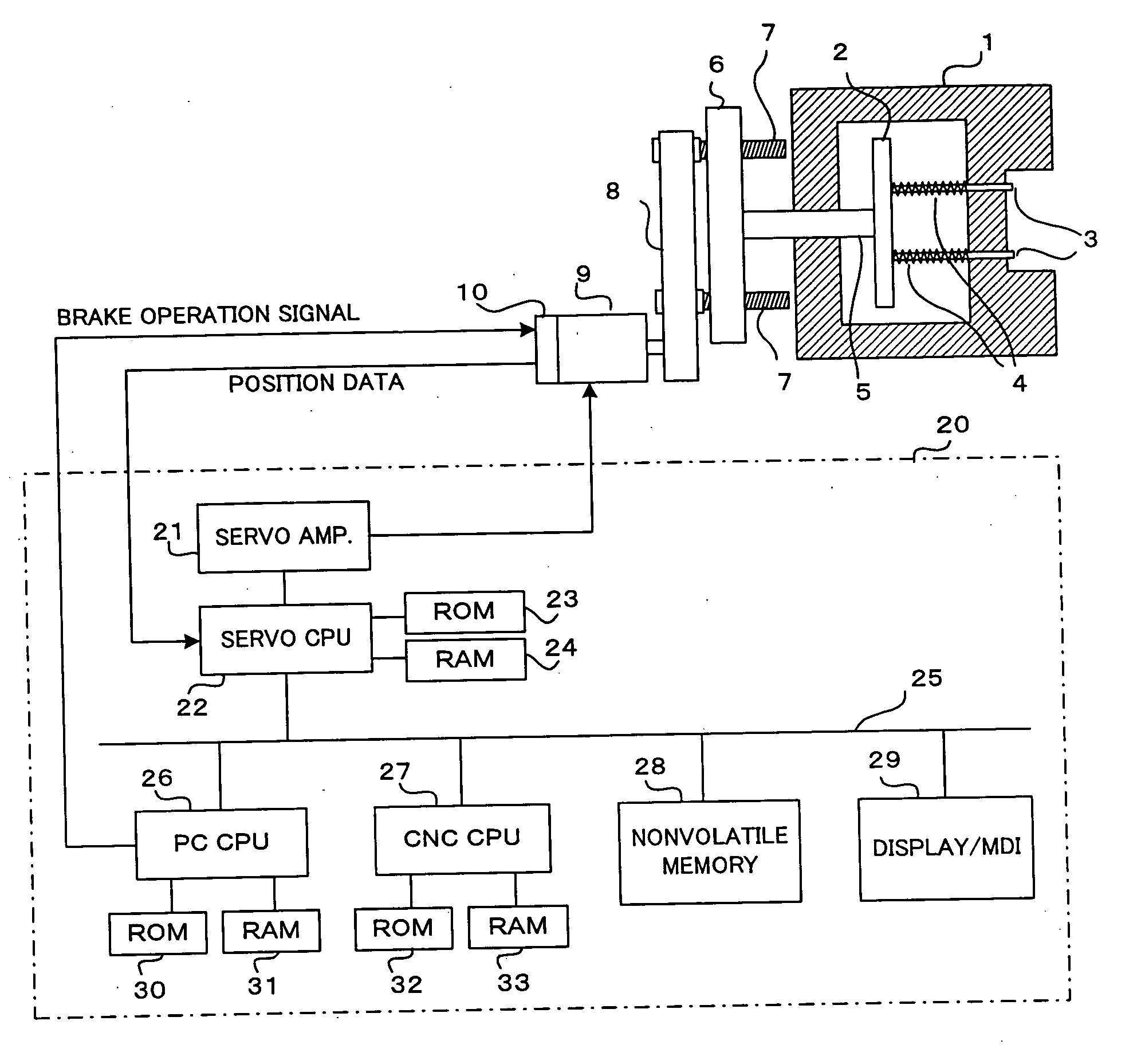
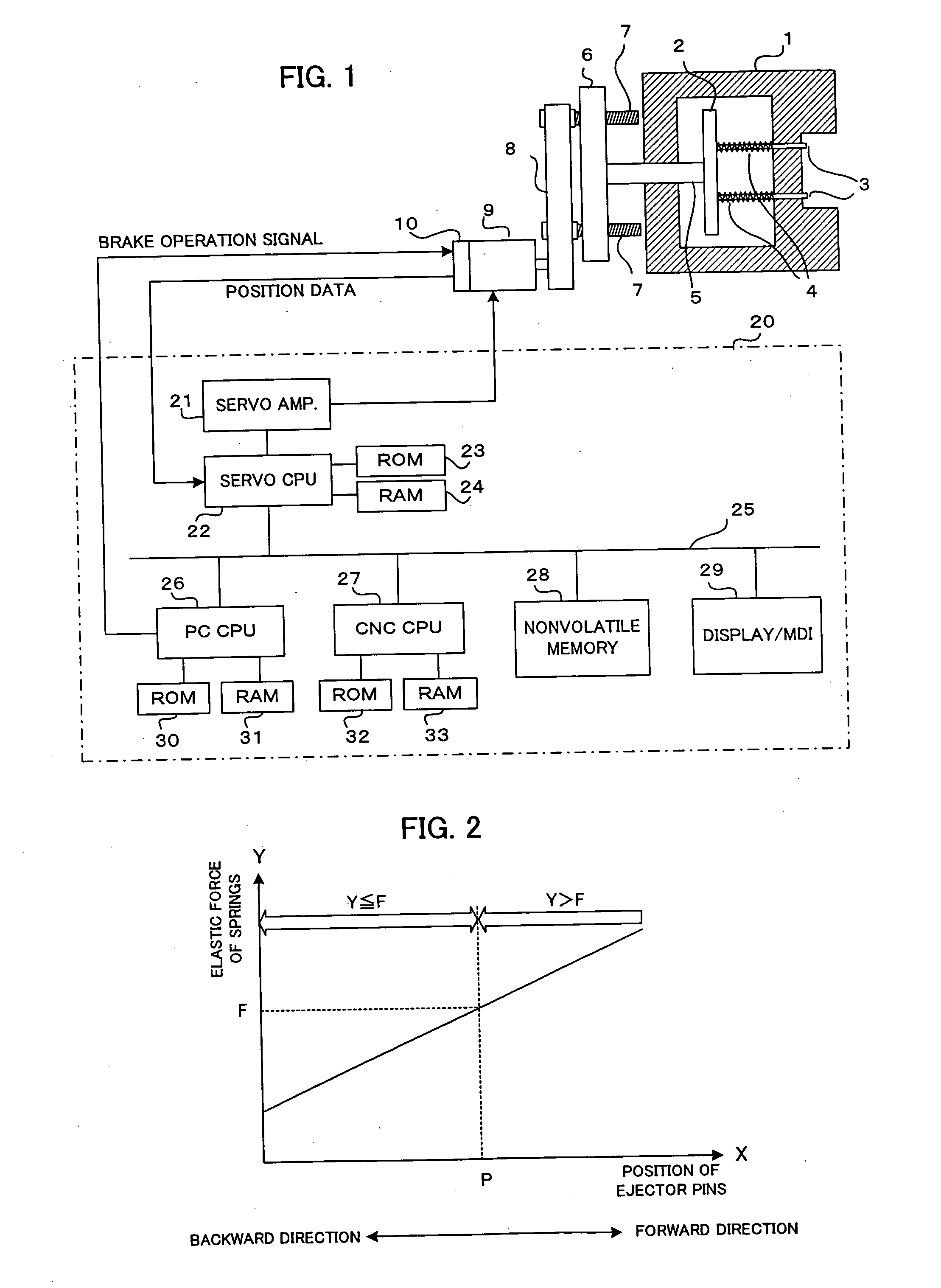
[0031] The CNC CPU 27 outputs a motion command to move the ejector pins 3 forward to a forward end position of a motion stroke of the ejector pins 3. The servo CPU 22 performs feedback controls of position and velocity to drive the servomotor 9 through the servo amplifier 21 according to the motion command (Step a1). Then, the CNC CPU 27 detects the elastic force of the springs 4 (Step a2). The elastic force is detected based on a ...

third embodiment

[0043]FIG. 5 is a flowchart of processing according to a

[0044] In this third embodiment, if the preset terminal position of the forward motion of the ejector pins is a position where the springs generate an elastic force exceeding the retaining force of the brake device, the terminal position of the forward motion of the ejector pins is automatically re-set to a position immediately before the position where the springs generate an elastic force exceeding the retaining force of the brake device.

[0045] In this third embodiment, the processing of Step c1 to Step c5 is the same as the processing of Step a1 to Step a5 in the first embodiment as shown in FIG. 3 and the processing of Step b1 to Step b5 in the second embodiment as shown in FIG. 4.

[0046] In this embodiment, the position of the ejector pins immediately before the springs generate an elastic force exceeding the retaining force of the brake device (the elastic force detected one period before the elastic force exceeds the re...


PUM

PropertyMeasurementUnit
Forceaaaaaaaaaa

Abstract

A controller and a method for an ejector mechanism in an injection molding machine for appropriately setting a terminal position of a forward motion of ejector pins of the ejector mechanism. The terminal position of the forward motion is set to a position where an elastic force of return springs does not exceed a retaining force of a brake device for retaining the ejector pins at the terminal position. The elastic force of the springs are detected during the ejector pins are moved forward. A position of the ejector pins immediately before the detected elastic force of the springs exceeds the retaining force of the brake device is determined and displayed on a display device as a criterial position. The terminal position of the forward motion of the ejector pins is set not to exceed the determined criterial position.

Description

BACKGROUND OF THE INVENTION [0001] 1. Field of the Invention [0002] The present invention relates to a controller of an ejector mechanism for ejecting a molded product from a mold in an injection molding machine, and also to a method of setting a terminal position of a forward motion of ejector pins of the ejector mechanism. [0003] 2. Description of Related Art [0004] In an injection molding machine, after resin is injected into a mold and concreted, the mold is opened and a molded product in the mold is ejected by an ejector mechanism. The ejector mechanism ejects a molded product by moving ejector pins forward to project into a cavity of the mold against an elastic force of return springs for returning the ejector pins to a retracted position. A pneumatic cylinder, a linear motor or a servomotor may be employed as a driving source for moving the ejector pins forward. A brake device is used for generating a retaining force to retain the ejector pins at a terminal position of the fo...

Claims


Application Information

Patent Timeline
IPC IPC(8): B29C45/40B29C45/76
CPCB29C45/4005B29C45/7626B29C2045/764B29C2945/76013B29C2945/76083B29C2945/7611B29C2945/76943B29C2945/76525B29C2945/76575B29C2945/76722B29C2945/76933B29C2945/76939B29C2945/76244
Inventor UCHIYAMA, TATSUHIROHOSOYA, YUICHI
Owner FANUC LTD
Why Eureka
Try Eureka