Variable magnification optical system, image taking lens device and digital apparatus

a technology of optical system and lens device, which is applied in the field of variable magnification optical system, image taking lens device and digital apparatus, can solve the problems of affecting the quality of images, so as to suppress the increase of cost and excellent optical performance

Inactive Publication Date: 2005-12-29
KONICA MINOLTA OPTO
View PDF8 Cites 66 Cited by
  • Summary
  • Abstract
  • Description
  • Claims
  • Application Information

AI Technical Summary

Benefits of technology

[0013] It is a main object of the present invention to provide compact variable magnification optical systems and image taking lens devices which are capable of exhibiting excellent optical ...

Problems solved by technology

Namely, the variable magnification optical system in the USP-A No. 2003-58548 includes many lenses and thus is inferior in the compactness, which makes it difficult to mount it on a portable phone or portable information terminal which are required to be miniaturized.
If an attempt is made to enhance the compactness of the variable magnification optical system of the U.S.-A No. 2002-149857, this will increase the difficulty of fabrication of lenses due to th...

Method used


Image

  • Variable magnification optical system, image taking lens device and digital apparatus
  • Variable magnification optical system, image taking lens device and digital apparatus
  • Variable magnification optical system, image taking lens device and digital apparatus

Examples


first embodiment

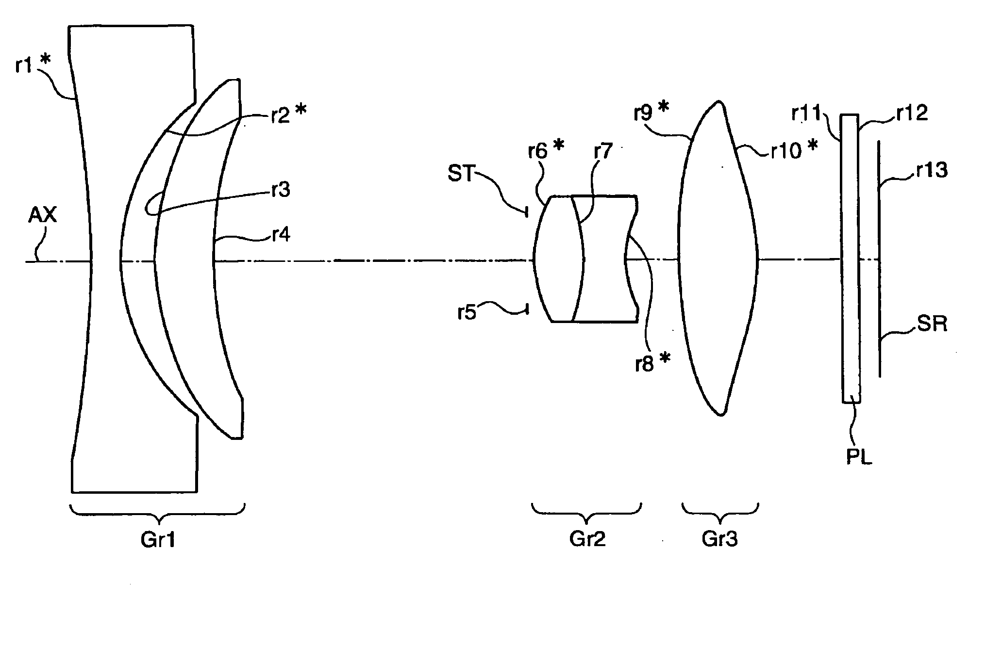
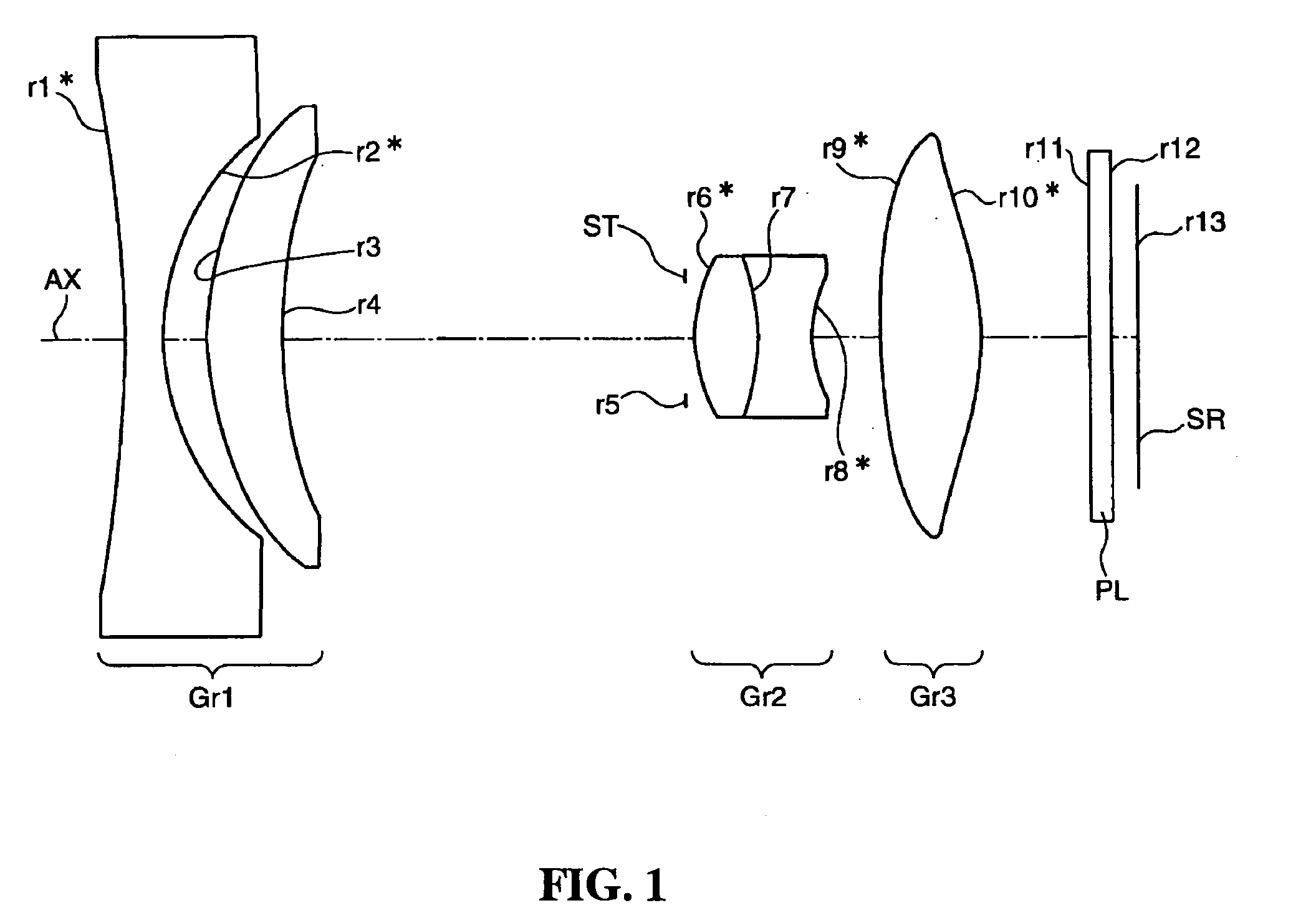
[0056]FIG. 1 is a cross sectional view illustrating the arrangement of the lens groups in a variable magnification optical system according to the first embodiment, along the optical axis (AX). FIG. 1 and FIGS. 2 to 7 illustrate the arrangement of lenses at the wide-angle end. Hereinafter, optical power is defined as the power when the medium at the both sides of the lens surface is air.

[0057] The variable magnification optical system according to the present embodiment is constituted by a first lens group (Gr1) having a negative optical power as a whole, an optical stop (ST) for adjusting the amount of light, a second lens group (Gr2) having a positive optical power as a whole and a third lens group (Gr3) having a positive optical power, which are placed in this order from the object side (the left side in FIG. 1). In the present embodiment, all of them are configured to be movable in a optical axis direction for magnification. At the opposite side of the third lens group (Gr3) fr...

second embodiment

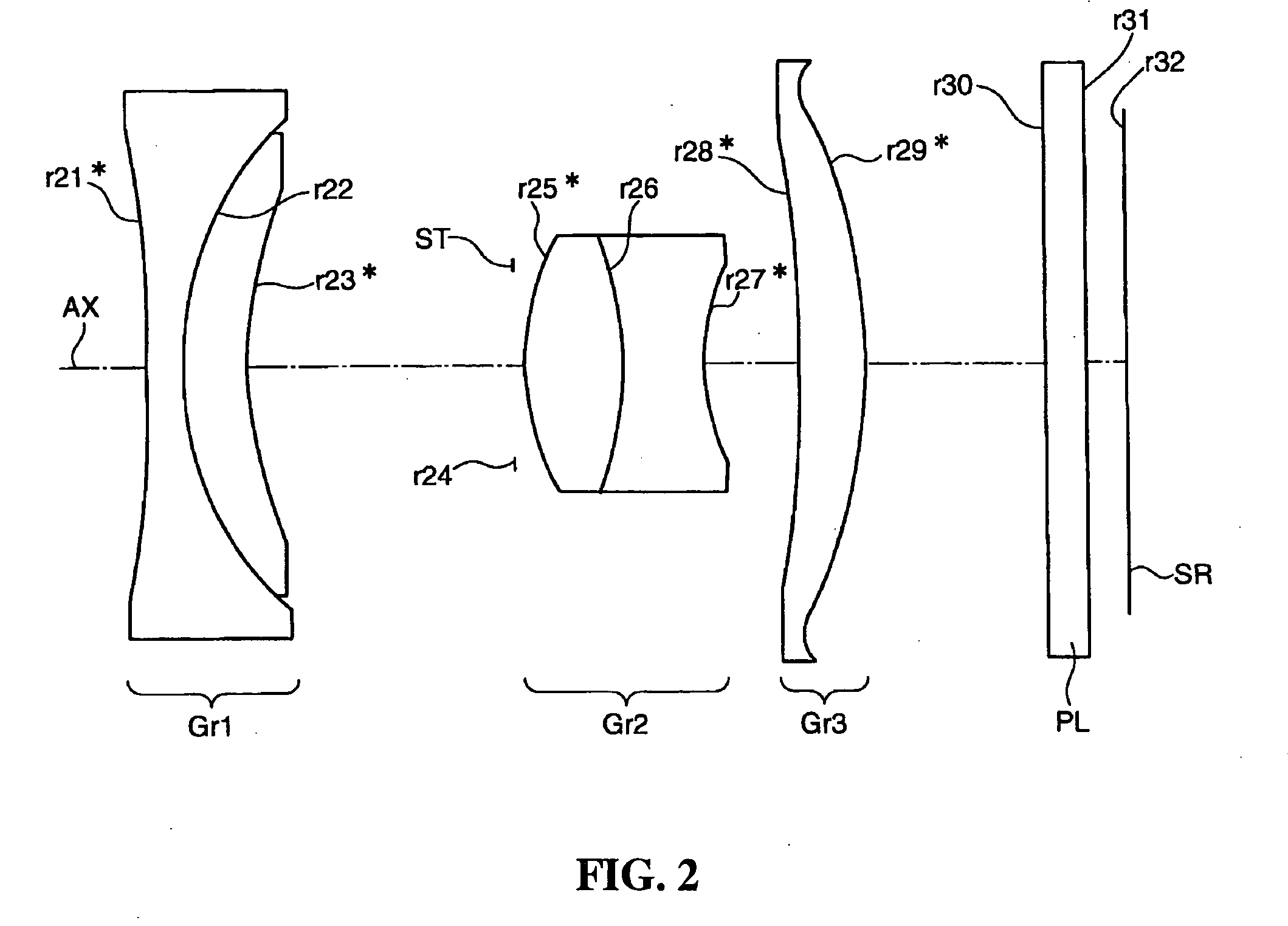
[0066]FIG. 2 is a cross sectional view illustrating the arrangement of the lens groups in a variable magnification optical system according to a second embodiment, along the optical axis (AX). The variable magnification optical system according to the second embodiment is constituted by a first lens group (Gr1) having a negative optical power as a whole, an optical stop (ST) for adjusting the amount of light, a second lens group (Gr2) having a positive optical power as a whole and a third lens group (Gr3) having a positive optical power, which are placed in this order from the object side. In the present embodiment, the optical stop (ST), the second lens group (Gr2) and the third lens group (Gr3) are configured to be movable in the optical axis direction during magnification, while the first lens group (Gr1) is fixed in the optical axis direction.

[0067] The first lens group (Gr1) is constituted by a bi-concave lens having a negative optical power and a positive meniscus lens which ...

third embodiment

[0069]FIG. 3 is a cross sectional view illustrating the arrangement of the lens groups in a variable magnification optical system according to the third embodiment, along the optical axis (AX). The variable magnification optical system according to the third embodiment is constituted by a first lens group (Gr1) having a negative optical power as a whole, an optical stop (ST) for adjusting the amount of light, a second lens group (Gr2) having a positive optical power as a whole, a third lens group (Gr3) having a positive optical power and a fourth lens group (Gr4) having a negative optical power, respective lens groups which are placed in this order from the object side. In the present embodiment, the first lens group (Gr1), the optical stop (ST), the second lens group (Gr2) and the third lens group (Gr3) are configured to be movable in the optical axis direction during magnification, while the fourth lens group (Gr4) is fixed in the optical axis direction.

[0070] The first lens grou...


PUM


Abstract

There are provided a first lens group having a negative optical power as a whole, second and third lens groups having positive optical powers as a whole, which are located in this order from the object side. These lens groups are all configured to be movable in the optical axis direction during magnification. The first lens group is constituted by a bi-concave lens having a negative optical power and a positive meniscus lens which is convex at the object side thereof, which are located in this order from the object side. The second lens group is constituted by a bi-convex lens having a positive optical power and a bi-concave power having a negative optical power, which are located in this order from the object side and bonded to each other to constitute a cemented lens. The third lens group is constituted by a bi-convex lens having a positive optical power. The first and fifth lenses are double-aspherical lenses formed from resin and the third and fourth lenses are single-aspherical lenses.

Description

[0001] The present application claims priority to Japanese Patent Application No. 2004-188852 filed Jun. 25, 2004, the entire content of which is hereby incorporated by reference. BACKGROUND OF THE INVENTION [0002] 1. Field of the Invention [0003] The present invention relates to variable magnification optical systems which are constituted by plural lens groups and capable of magnification by varying the spacing of the respective lens groups in the optical axis direction, an image taking lens device including the variable magnification optical system and digital apparatus incorporating the image taking lens device. [0004] 2. Description of the Related Art [0005] In recent years, widespread use of portable phones and portable information terminals (PDA: Personal Digital Assistant) have been remarkable, and furthermore such devices incorporating a compact digital still camera unit or digital video unit have become common. Since there are severe constraints on the size and cost of thes...

Claims


Application Information

Patent Timeline
IPC IPC(8): G02B13/00G02B15/14G02B15/177
CPCG02B13/0035G02B13/004G02B15/177G02B13/009G02B13/006G02B15/143507G02B15/144507
Inventor MATSUSAKA, KEIJI
Owner KONICA MINOLTA OPTO
Why Eureka
Try Eureka