Zoom lens assembly

a technology for zoom lenses and lens sets, applied in the field of zoom lens assemblies, can solve the problems of difficult to guarantee the optical performance of the zoom lens assembly, performance degradation, and inability to completely ensure the structure, so as to reduce sliding friction, facilitate the sliding of the lens, and provide the compact sliding surface

Inactive Publication Date: 2005-12-29
ASIA OPTICAL INT LTD
View PDF4 Cites 4 Cited by
  • Summary
  • Abstract
  • Description
  • Claims
  • Application Information

AI Technical Summary

Benefits of technology

[0008] An object of the present invention is to provide a zoom lens assembly capable of assuring that each lens is coaxial with each other and stabile even during oppositely moving and assembly. The image quality can be therefore raised and a simplified structure is incorporated for easily using and adjusting.
[0010] A further object of the present invention is to provide a zoom lens assembly that comprises at least two lens sets mated and slidable in response to each other, and a shallow groove is formed on a precise sliding surface for providing the compactness of the sliding surfaces and diminishing the friction between the sliding surfaces.
[0011] According above objects of the present invention, there is provided a zoom lens assembly comprising a plurality of optical lenses, at least two internal barrels, a lens holder and an alignment element, wherein the lenses can be divided into at least two lens groups. The two internal barrels are used to retain corresponding lens group respectively and formed the first and second lens sets, and a portion of the internal barrel which retains one lens group is contained in the other internal barrel which retains another lens group after assembled. The lens holder is used to contain the first and second lens set. The alignment element can assure that each lens group of the lens set is in the same axis after assembled. The alignment element comprises at least a structure and a sliding device, wherein the structure is used for precisely coupling at least one portion of the two internal barrels. The sliding device utilizes at least a fastening device to combine the mating structure formed on two lens sets to a guiding groove on the lens holder, thereby the lens sets can slide in the lens holder.
[0013] The shallow groove is formed on the sliding surfaces between the two internal barrels for providing the compactness of the sliding surfaces and diminishing the sliding friction between the sliding surfaces in order to prevent the surfaces are stuck each other caused by the closely coupling of two internal barrels and good for the movement thereof. In addition, there is a vent formed on the sidewalls of the main body of one lens set for eliminating the pressure differentials between two lens sets to help the lens sets slide smoothly.
[0014] In contrast to the prior art, the zoom lens assembly according to the present invention assures that each lens keep in the same axis after assembled and increases the stability during moving mutually by the two alignments of the alignment element and the optical qualities thereof can be improved. Furthermore, since each lens group is combined into a single body already while mounting in the lens holder, the stability of the assembled process can be improved and the assembled procedures can be simplified to overcome the disadvantages of the conventional assembled method.

Problems solved by technology

In optical industry, any one of the lens sets has to be kept extremely controlled in a concentric and coaxial manner, even many times during opposite movements between the lens sets, in order to prevent the lens sets from becoming eccentric or non-coaxial after the assembly to result in performance degradation.
Such a structure is not capable to completely ensuring that the first and second lens groups 90, 91 are moved oppositely along the same optical axis for all the time.
Thus, it is hard to guarantee the optical performances of the zoom lens assembly.

Method used


Image

  • Zoom lens assembly
  • Zoom lens assembly
  • Zoom lens assembly

Examples


Embodiment Construction

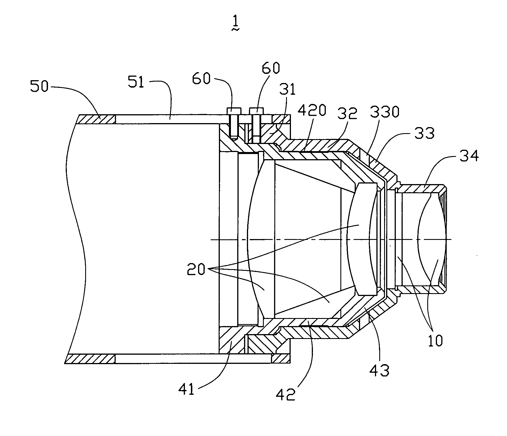
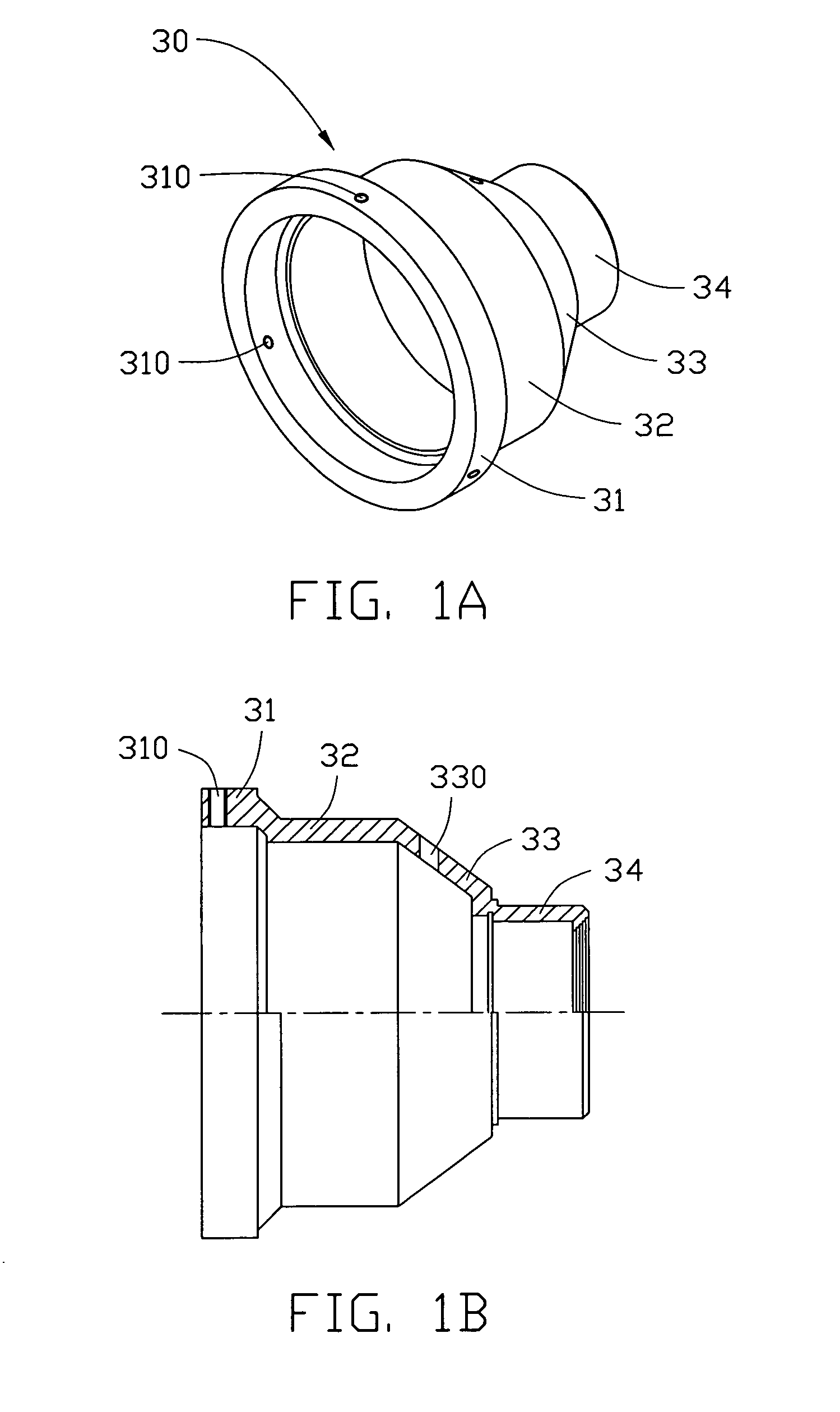
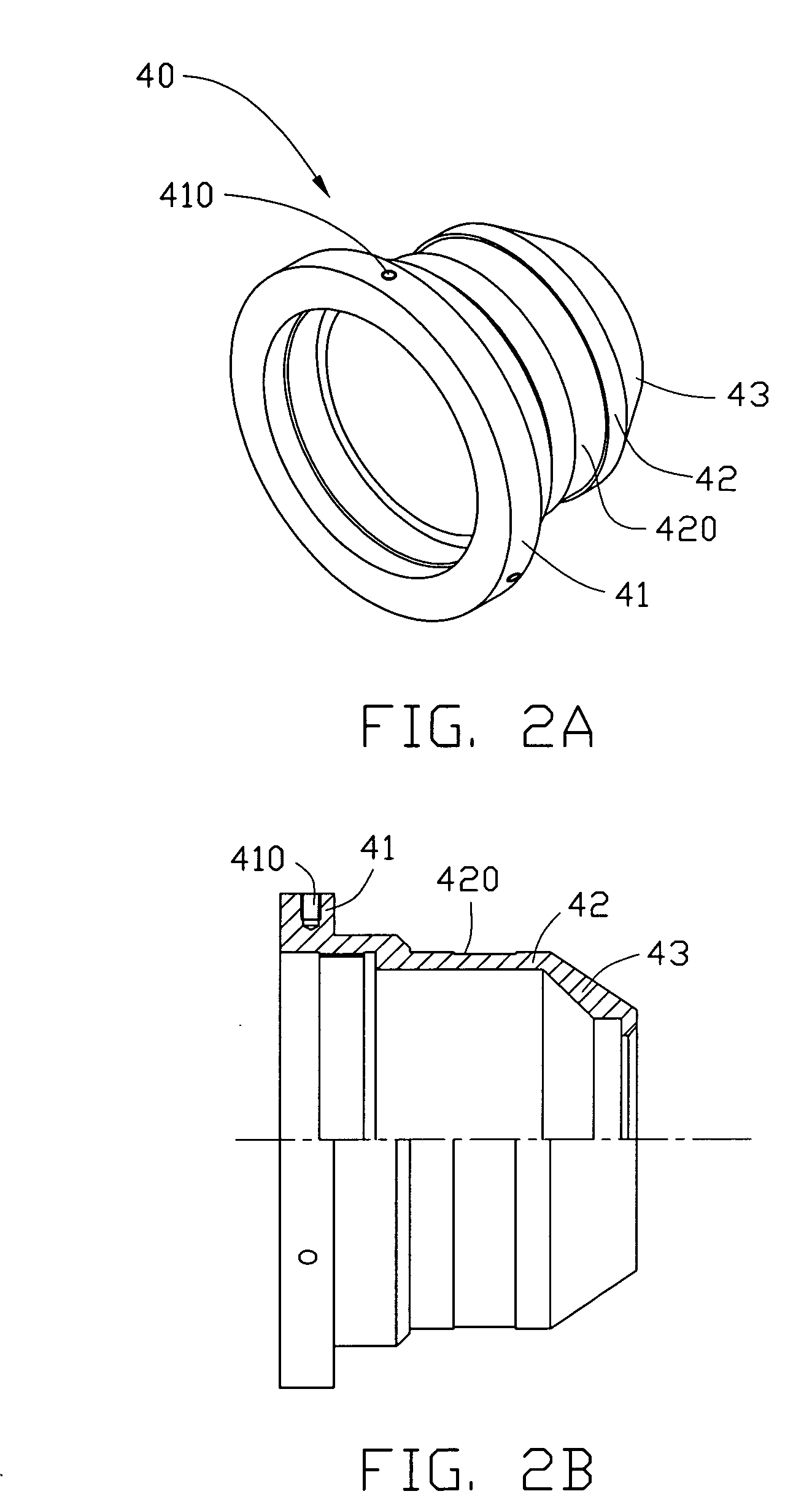
[0023] The present invention will now be described more specifically with reference to the following embodiments. It is to be noted that the following description of the preferred embodiments of the present invention are presented herein for purpose of illustration and description only and it is not intended to be exhaustive or to be limited to the precise form disclosed.

[0024] With reference to FIG. 1A to FIG. 4, a zoom lens assembly 1 according to a preferred embodiment of the present invention is disclosed. The zoom lens assembly 1 comprises a plurality of optical lenses divided into a first and second lens groups 10, 20, and a first and second internal barrels 30, 40. Meanwhile, the first lens group 10 (as a front lens group) is mounted in the first internal barrel 30 to form a first lens set and the rear lens group 20 (as a rear lens group) is mounted in the second internal barrel 40 to form a second lens set. After the two lens sets are assembled, the second internal barrel 4...


PUM


Abstract

The present invention discloses a zoom lens assembly with capability of assuring concentricity of at least a lens group even during activity. The zoom lens assembly includes a plurality of optical lenses, at least two internal barrels, a lens holder and an alignment element wherein the lenses can be divided into at least two lens groups. The two internal barrels are used to respectively retain corresponding lens group therein to define a first and second lens sets. The lens holder is utilized to accommodate the first and second lens set therein. After twice alignment procedures in an assembled method, an internal barrel retained with one lens group is accommodated within the other internal barrel retained with another lens group to be precisely coupled. The two lens sets with mating structures are coupled to a guiding groove defined on the lens holder thereby the lens sets can slide inside the lens holder.

Description

BACKGROUND OF THE INVENTION [0001] 1. Field of the Invention [0002] The present invention relates to a zoom lens assembly, and more specifically, to a zoom lens assembly adapted for an apparatus capable of projecting or photographing. [0003] 2. The Related Art [0004] Due to successive developments on the recent electronic products, especially on a projecting and photographing apparatus, their essential corresponding optical elements have to be raised with great precision in compliance with the requirements of qualities and the optimum image effects. A common character appearing in the above apparatus should have an ability of how to implement optically zooming by using an optical lens. Physically, the lens has a utility of being moveable to carry out zooming in / out of an image. Therefore, made as an essential optical element of the above apparatus, the performance of any image is absolutely depended on whether the fabrication quality of the optical lens is great or not. [0005] Gener...

Claims


Application Information

Patent Timeline
Patent Type & Authority Applications(United States)
IPC IPC(8): G02B7/10G02B15/14
CPCG02B7/10
Inventor CHEN, KUN-MING
Owner ASIA OPTICAL INT LTD
Why Eureka
Try Eureka