
Battery holder

a battery and holder technology, applied in the field of batteries, can solve the problems of shortening the life of batteries, affecting the reliability of batteries, and laborious de-soldering and re-soldering operations, and achieve the effect of reliable and convenient mounting of batteries

Inactive Publication Date: 2005-12-29
HTC CORP
View PDF7 Cites 13 Cited by
  • Summary
  • Abstract
  • Description
  • Claims
  • Application Information

AI Technical Summary

Benefits of technology

[0009] Accordingly, an objective of the present invention is to provide a battery holder that ensures a reliable and convenient mounting of a battery on a printed circuit board and dispenses with the need to conduct a soldering operation to the battery.
[0010] A second objective of the present invention is to provide a battery holder that is low cost and mounted to a printed circuit board by surface mounting technology. Furthermore, the battery holder facilitates a proper position of a battery in the battery holder, and an easy and safe replacement of the battery with a new battery when required.

Problems solved by technology

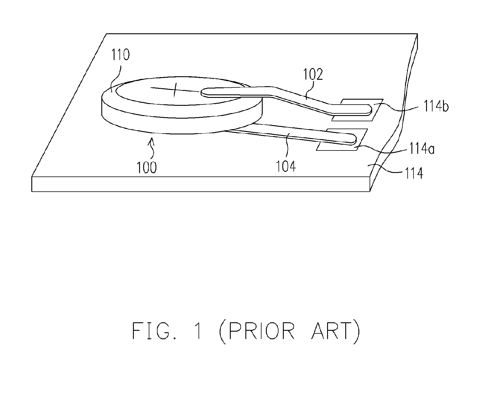
Such de-soldering and re-soldering operations are very laborious.
Moreover, with the anode of the battery 100 facing up without any protection, an operator may carelessly touch the anode of the battery 100, which may cause damage to the battery 100 and shorten the life thereof.
When this happens, the battery 100 and / or associated circuits may be damaged.
Although the disclosed design is more reliable and convenient to mount a battery on a printed circuit board than the one shown in FIG. 1, a large number of small and complicated components are required to construct the battery holder of the U.S. Pat. No. 6,124,056; so the cost for producing this battery holder is high.

Method used


Image

  • Battery holder
  • Battery holder
  • Battery holder

Examples


Embodiment Construction

[0025] Reference will now be made in detail to the present preferred embodiment of the invention, examples of which are illustrated in the accompanying drawings. Wherever possible, the same reference numbers are used in the drawings and the description to refer to the same or like parts.

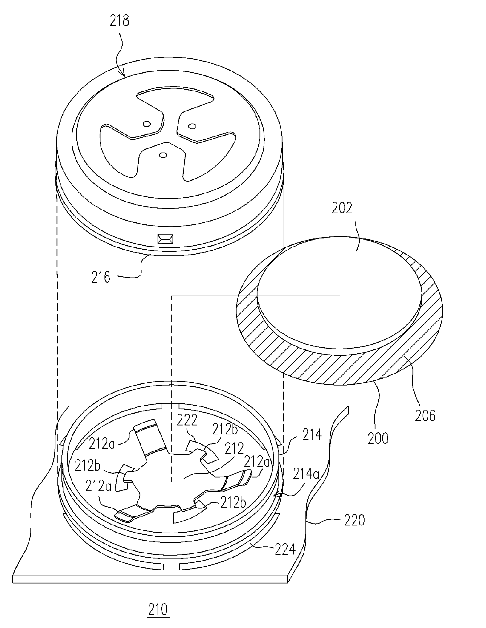
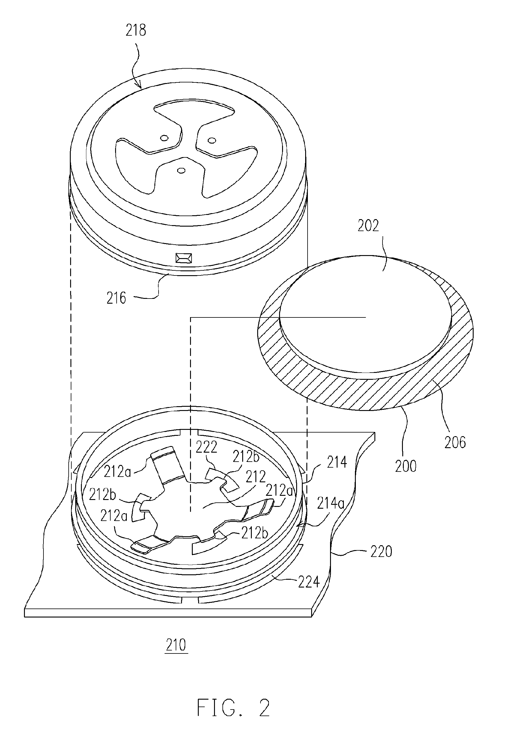
[0026] Referring to FIG. 2, the present invention is a battery holder 210 for mounting a battery 200 to a printed circuit board 220. The battery 200 is a button-type battery used as a back-up battery in a handheld electronic device (not shown) to supply power to the device when the main power supply of the device incidentally runs out. The battery 200 has a positive electrode (anode) (not labeled) and a negative electrode (cathode) 202 located at bottom and the top surfaces of the battery 200, respectively. An insulation 206 surrounds a periphery of the battery 200 to separate the positive electrode from the negative electrode 202.

[0027] Still referring FIG. 2, the battery holder 210 mainly compris...


PUM

PropertyMeasurementUnit
flexibleaaaaaaaaaa
resilientaaaaaaaaaa
poweraaaaaaaaaa

Abstract

A battery holder (210) for mounting a button-type battery (200) on a printed circuit board (220) is provided. The battery holder comprises a resilient electrode plate (212), a ring (214) and a battery cap (216). The resilient electrode plate is soldered to positive contacts (222) of the printed circuit board. An anode of the battery is put on and electrically connects with the resilient electrode plate to thereby connect electrically with the positive contacts on the printed circuit board. The ring is soldered to negative contacts (224) of the printed circuit board and surrounds the resilient electrode plate. The battery is accommodated within the ring. The battery cap is fixed and electrically connected to the ring and covers the battery. The battery cap also electrically contacts with a cathode (202) on a top of the battery. The cathode and anode of the battery are separated by an insulation (206).

Description

CROSS-REFERENCE TO RELATED APPLICATION [0001] This application claims the priority benefit of Taiwan application serial no. 93210182, filed Jun. 29, 2004. BACKGROUND OF THE INVENTION [0002] 1. Field of the Invention [0003] The present invention relates to a battery holder. More particularly, the present invention relates to a battery holder for mounting a button type battery on a printed circuit board. [0004] 2. Description of the Related Art [0005] In the modern world of rapid changes, up to the minute information is transmitted through a system of networks. All kinds of electronic products including mobile phones, computers and audio-visual equipments are indispensable in our daily life. With the repeated advance in electronic technologies, more personalized and multifunctional electronic products are sold in the market. As the number of portable products proliferates, the need of backup batteries also increases. A backup battery, which usually is button type or coin type battery,...

Claims


Application Information

Patent Timeline
Patent Type & Authority Applications(United States)
IPC IPC(8): H01M2/10H05K3/30H05K3/34
CPCH01M2/1044H01R12/57H05K3/301H05K2201/10643H05K2201/1031H05K2201/10393H05K3/341H01M50/216Y02E60/10Y02P70/50
Inventor YEH, JIH-CHEN
Owner HTC CORP
Learn More