
Housing case for electronic circuit board

Active Publication Date: 2005-12-29
HITACHI ASTEMO LTD
View PDF12 Cites 15 Cited by
  • Summary
  • Abstract
  • Description
  • Claims
  • Application Information

AI Technical Summary

Benefits of technology

[0009] Therefore, an object of the present invention is to solve the above-described drawback and to provide a housing case for an electronic circuit board which can easily receive the electronic circuit board to be accurately fixed at a predetermined position, while preventing an excessive twisting / shaking force from concentrating at a joint where components are joined to the electronic circuit board, when mating connector is inserted to or removed from the components.

Problems solved by technology

The twisting / shaking force disadvantageously acts to increase the stress on the joints, thereby rendering the electrical connections between the connectors and the electronic circuit board unstable.

Method used


Image

  • Housing case for electronic circuit board
  • Housing case for electronic circuit board
  • Housing case for electronic circuit board

Examples


Embodiment Construction

[0020] The preferred embodiment of a housing case for an electronic circuit board according to the present invention will be described below with reference to the attached drawings.

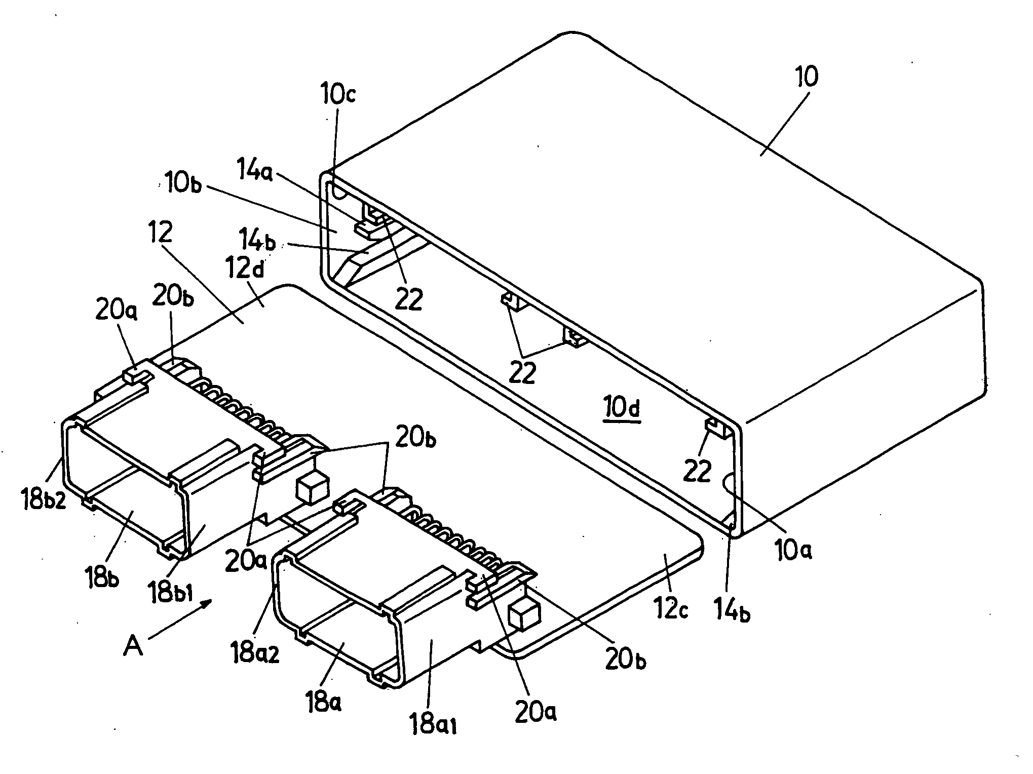
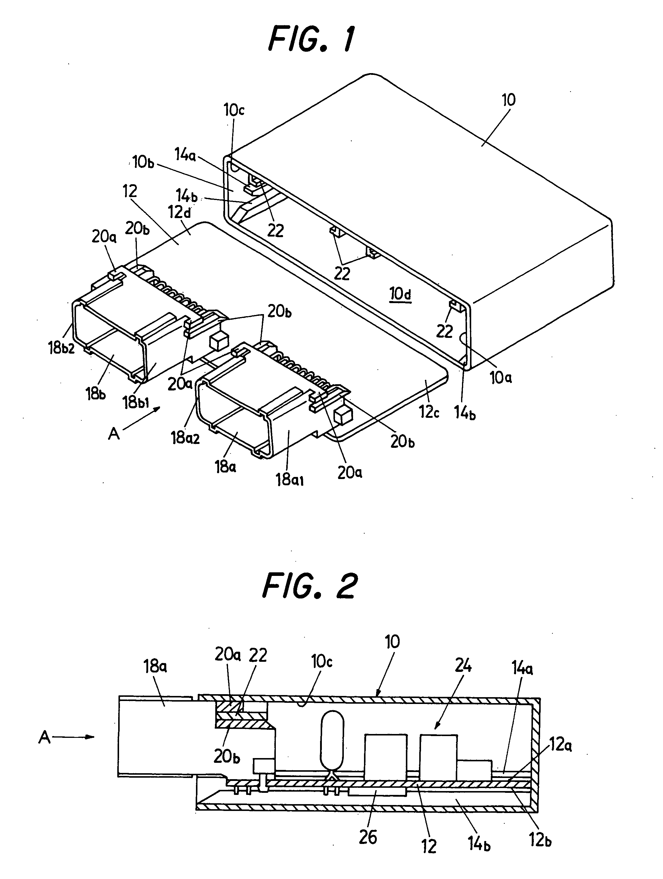
[0021]FIG. 1 is a perspective view showing a housing case for the electronic circuit board according to an embodiment of the present invention, and the electronic circuit board on which connectors are mounted; and FIG. 2 is a cross-sectional schematic view showing the electronic circuit board, illustrated in FIG. 1, on which the connectors and other components are mounted, housed in the housing case.

[0022] The housing case 10 has a substantially rectangular (tube-like) shape that is opened at one end and is made of resin. Two (a pair of) guide rails 14a and 14b that form a guide path for guiding the electronic circuit board (hereinafter simply referred to as “board”) 12 are respectively formed on the inside walls 10a and 10b of the side surfaces (side surfaces when viewed from the insertion direction (d...


PUM


Abstract

In a housing case for an electronic circuit board on which components such as connectors are mounted, there are provided a pair of guide rails that form a guide path when the board is inserted in the case and a holder holding the connectors mounted on the board, and the guide rails are disposed in a position that does not interfere with the board when the connector is held by the holder, thereby enabling to easily receive the board to be accurately fixed at a predetermined position, while preventing an excessive twisting / shaking force from concentrating at a joint where components are joined to the board, when mating connector is inserted to or removed from the connectors.

Description

BACKGROUND OF THE INVENTION [0001] 1. Field of the Invention [0002] The present invention relates to a housing case for an electronic circuit board, more particularly to a housing case for an electronic circuit board provided with a pair of guide rails that form a guide path for guiding the electronic circuit board. [0003] 2. Description of the Related Art [0004] Conventionally, the housing cases for housing the electronic circuit boards on which connectors, electronic parts and other components are integrally mounted or fixed are configured such that the electronic circuit board can be easily inserted and fixed at a predetermined position in the housing case, as disclosed, for example, in Japanese Laid-Open Patent Application No. 2001-237557 (from paragraph 0031 to 0034, FIG. 1, etc.). [0005] Specifically, in the technique taught in '557, the connectors are fixed on the electronic circuit board by soldering the distal portions of connection terminals of the connectors on the board,...

Claims


Application Information

Patent Timeline
IPC IPC(8): H01R12/00H05K5/00H05K5/02H05K7/14
CPCH05K5/0039
Inventor KITAMURA, NOBUYUKI
Owner HITACHI ASTEMO LTD
Learn More