Assembly for holding plastic film within a mold

a technology of plastic film and mold, which is applied in the direction of turning apparatus, food shaping, food science, etc., can solve the problems of discoloration and tearing of plastic film

Inactive Publication Date: 2006-03-14
AP PLASMAN INC
View PDF10 Cites 13 Cited by
  • Summary
  • Abstract
  • Description
  • Claims
  • Application Information

AI Technical Summary

Benefits of technology

[0008]The interface is defined by upper and lower surfaces on the upper and lower mold sections. The plastic film is held within a gap between the upper and lower surfaces. Each of the surfaces also defines a width. The gap and width of the interface determine the amount of clamping force exerted on the plastic film when the mold sections are closed. The clamping force prevents plastic injected at high pressure into the cavity from shifting the plastic film during molding. The level of clamping force is balanced to prevent excessive application of force that can damage or crush the plastic film.
[0011]The configuration of the mold tool of this invention provides proper application of clamping force on the plastic film to secure the plastic film, while not causing damage to the plastic film.

Problems solved by technology

Although plastic film includes many advantages over the use of paint films, the use of plastic film presents several design and processing challenges.
Crushing of the color layer may cause discoloration and tearing of the plastic film.

Method used


Image

  • Assembly for holding plastic film within a mold
  • Assembly for holding plastic film within a mold
  • Assembly for holding plastic film within a mold

Examples


Embodiment Construction

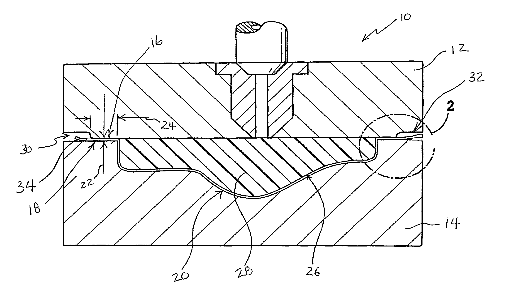
[0015]Referring to FIGS. 1, 2 a mold tool 10 is shown and includes upper and lower sections 12, 14. The upper and lower sections 12,14 of the mold 10 cooperate to form a cavity 20. Surfaces 16, 18 disposed about a perimeter 32 of the cavity 20 form an interface 30 to secure the plastic film 26 within the mold 10. Preferably, the plastic film 26 is preformed into a desired shape and inserted into the mold 10. A portion 34 of the plastic film 26 is trapped between the upper and lower sections 12,14 of the mold 10 at the interface 30.

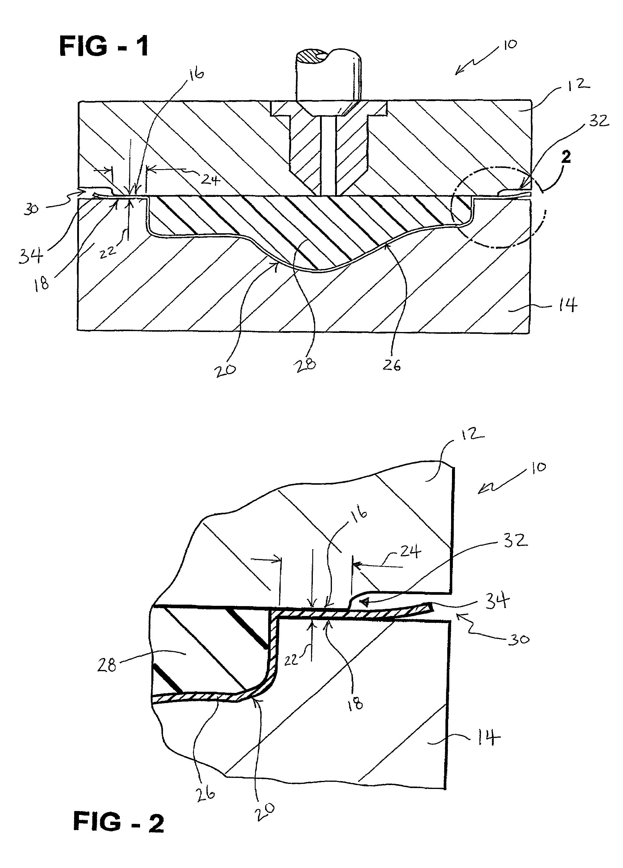
[0016]Referring to FIG. 2, the interface 30 is defined by the upper surface 16 on the upper mold portion 12 and the lower surface 18 disposed on the lower mold portion 14. The plastic film 26 is held within a gap 22 between the upper and lower surfaces 16, 18. Each of the surfaces 16, 18 also defines a width 24. The gap 22 and width 24 of the interface 30 determine the amount of clamping force exerted on the plastic film 26 when the mold sections 12, 14 ar...


PUM

PropertyMeasurementUnit
thicknessaaaaaaaaaa
compressive strenghtaaaaaaaaaa
pressureaaaaaaaaaa

Abstract

A mold tool includes upper and lower sections defining a cavity within which a plastic film preform is placed before injection of plastic forming a molded article. The plastic film extends between an interface defined between the sections of the mold. The interface secures a position of the plastic film within the mold tool preventing movement during injection of plastic. The interface is specifically configured to secure the plastic film without damage. The specific configuration of the interface is determined according to a relationship between molding process parameters and physical characteristics of the plastic film.

Description

[0001]This application claims priority to provisional application Ser. No. 60 / 281,813 filed on Apr. 5, 2001.BACKGROUND OF THE INVENTION[0002]The invention relates to an assembly and method of holding plastic film within a mold.[0003]In-mold decorating is a term of art describing the process of applying a decorative coating to a plastic part during the molding process. Conventional methods of applying a decorative coating include the use of a paint film placed within the mold that adheres to a plastic substrate injected into the mold during the molding process. A currently known alternative to the use of paint film is the use of a plastic film. The use of plastic film provides several advantages over the use of paint film. The plastic film can stretch to a greater extent than plastic film, allowing application to complex and intricate shapes. Further, plastic film provides the same color matching capabilities as do paint films. Finally, plastic film is formed of substantially the sam...

Claims


Application Information

Patent Timeline
Patent Type & Authority Patents(United States)
IPC IPC(8): B29C45/14B29C45/80
CPCB29C45/14262B29C2045/1427
Inventor SCHMIDT, HORST
Owner AP PLASMAN INC
Why Eureka
Try Eureka