Electric storage device and rechargeable battery

a technology of electric storage device and rechargeable battery, which is applied in the direction of cell components, sustainable manufacturing/processing, and final product manufacturing, etc., can solve the problems of degrading battery performance, unable to fulfill and unable to meet the function of the battery

Active Publication Date: 2015-04-09
TOYOTA IND CORP
View PDF2 Cites 12 Cited by
  • Summary
  • Abstract
  • Description
  • Claims
  • Application Information

AI Technical Summary

Benefits of technology

[0009]An object of the present invention is to provide an electric storage device and a rechargeable battery capable of preventing excessive force from being applied to the electrode sheets.
[0011]According to this configuration, the edge of the active material layer of the positive electrode sheet can be positioned on the imaginary boundary plane or in an area more distant from the secondary inner wall surface to which the edge is opposed than the position of the imaginary boundary plane. As a result, the edge of the positive electrode sheet can be prevented from being placed over the corner surface, and the positive electrode sheet serving as an electrode sheet is prevented from receiving an excessive force.
[0013]According to this configuration, the edge of the active material layer of each positive electrode sheet can be positioned on the imaginary boundary plane or in an area more distant from the secondary inner wall surface to which the edge is opposed than the position of the imaginary boundary plane. As a result, the edge of the positive electrode sheet is prevented from being placed over the corner surface, and the positive electrode sheet serving as an electrode sheet is prevented from receiving excessive force.

Problems solved by technology

Thus, pressure is locally applied to portions opposed to corner portions of the plate group 65, positive electrode sheets, negative electrode sheets, and separators, which constitute the electrode assembly, therefore leading to degradation of the battery performance.
In the case of a lithium-ion battery for example, lithium is deposited particularly on a part of the positive electrode sheets, to which part pressure is locally applied, and then the function of the battery cannot be fulfilled.
Not applied only to the rechargeable battery, the same problem can arise in a capacitor such as an electric double layer capacitor and a lithium-ion capacitor.

Method used


Image

  • Electric storage device and rechargeable battery
  • Electric storage device and rechargeable battery
  • Electric storage device and rechargeable battery

Examples


first embodiment

[0035]Hereinafter, a rechargeable battery according to a first embodiment of the present invention will be described with reference to FIGS. 1 and 2.

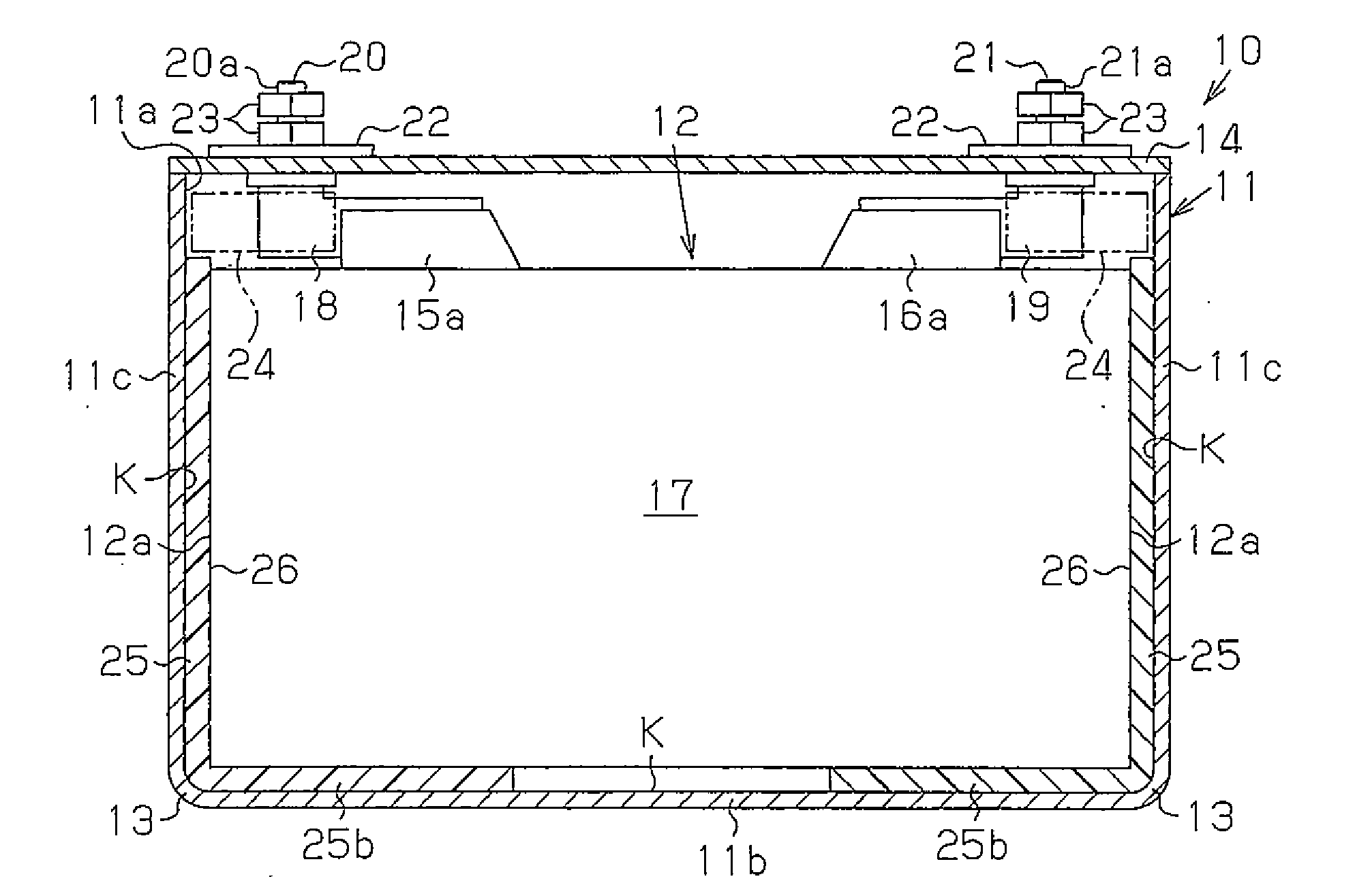
[0036]As shown in FIG. 1(a), a laminated-type electrode assembly 12 is accommodated within a case main body 11 of a rechargeable battery 10 serving as an electric storage device.

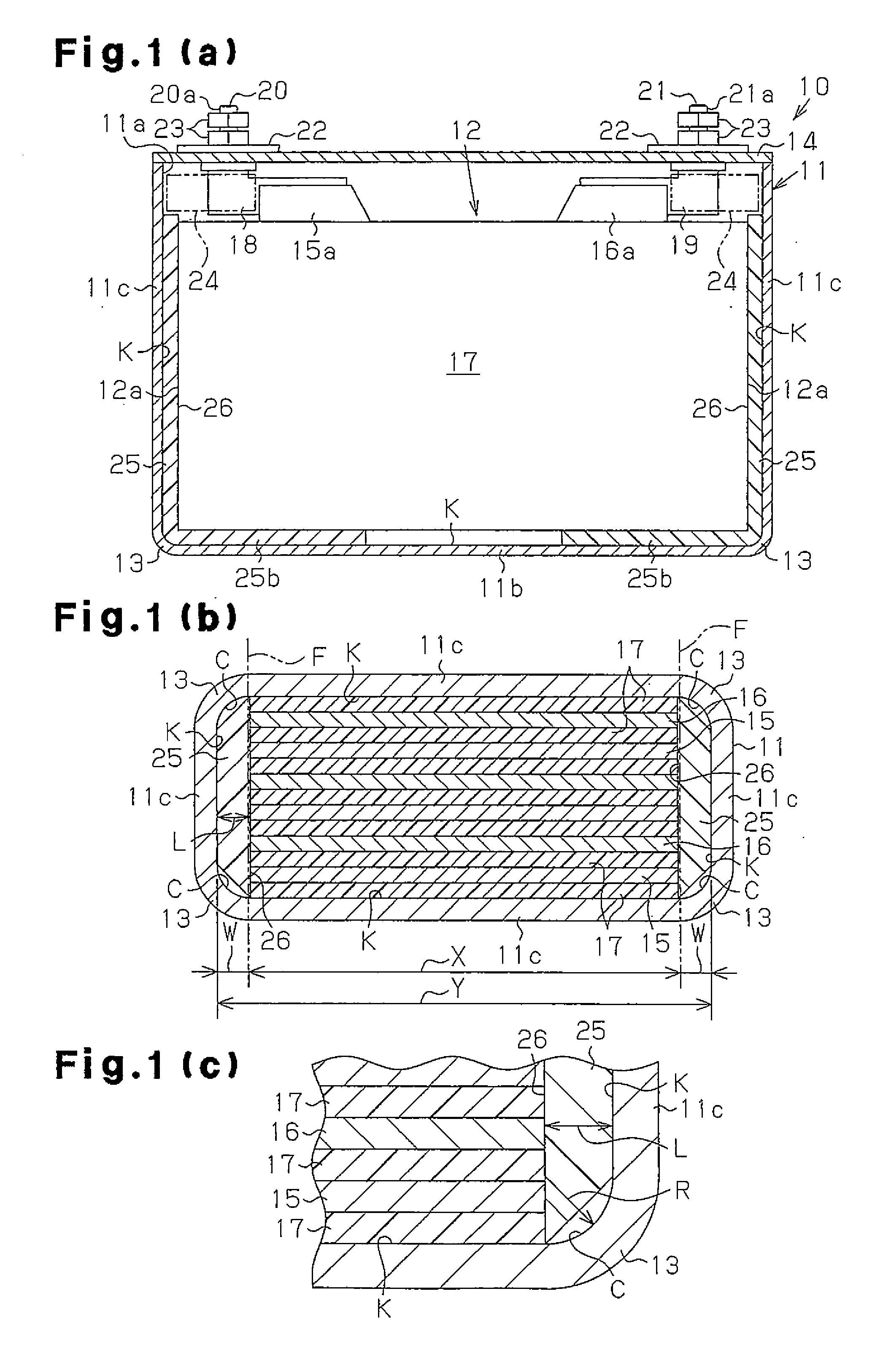
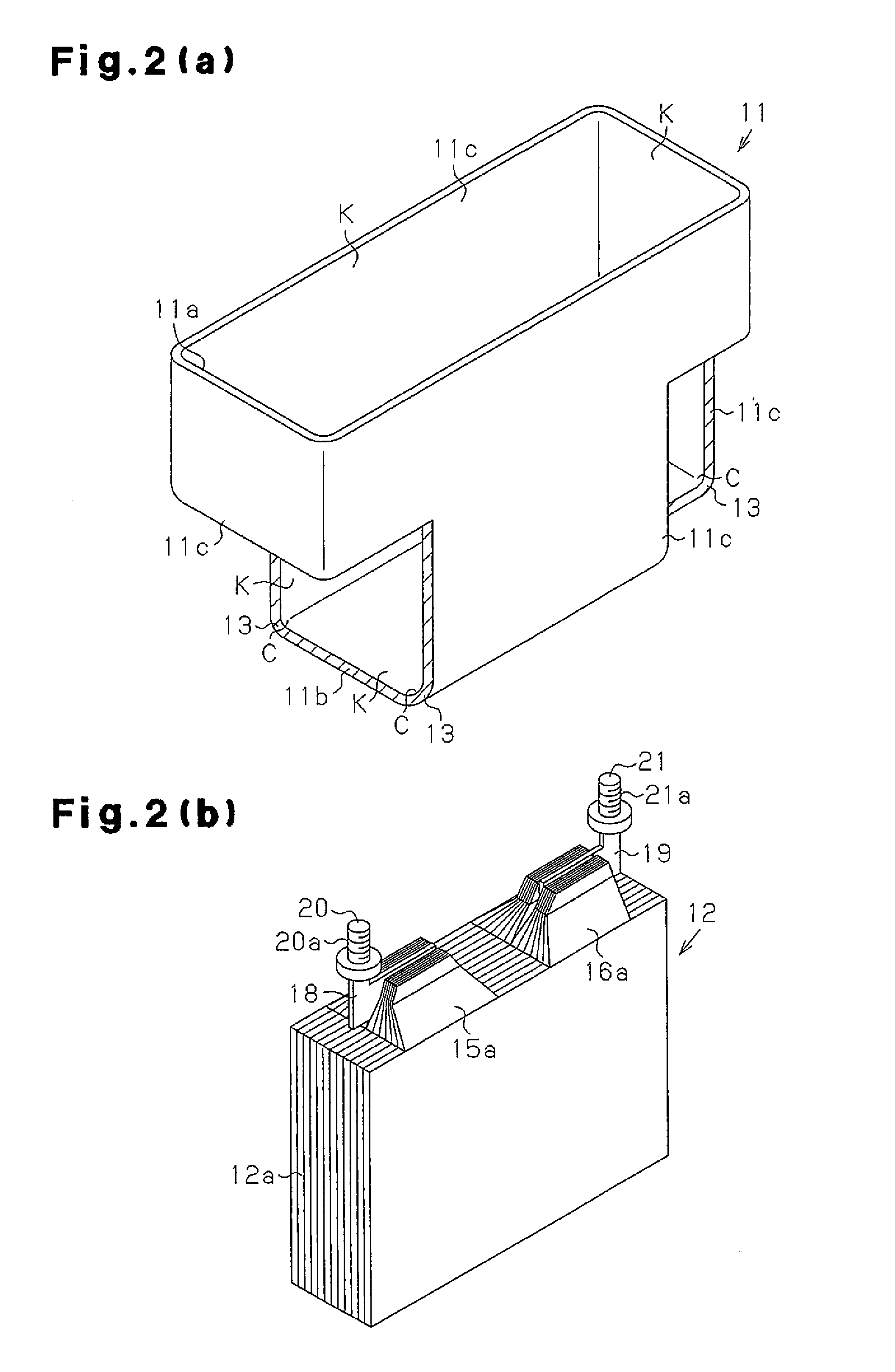
[0037]The case main body 11 has a rectangular tubular shape with a closed end. In four corners extending from an opening portion 11a to a bottom wall 11b, the case main body 11 has curved portions (arcuate portions) 13 round in a cross-section perpendicular to a direction in which the four corners extend, as shown in FIGS. 1(b) and 1(c). In each peripheral edge of the bottom wall 11b, the case main body 11 also has a curved portion 13 round in a cross-section perpendicular to a direction in which each peripheral edge extends, as shown in FIG. 2(a). More specifically, the case main body 11 has the curved portions 13 as corner portions at parts where the bottom wa...

second embodiment

[0063]Next, a second embodiment will be described with reference to FIGS. 3 and 4. The second embodiment differs from the first embodiment in shapes of the case main body and the lid body. Like or the same reference numerals are given to those components that are like or the same as the corresponding components of the first embodiment, and detailed explanations are omitted.

[0064]As shown in FIGS. 3 and 4, an opening portion 31a has a shape larger than the outer shapes of the positive electrode sheets 15, the negative electrode sheets 16, and the separators 17 of the electrode assembly 12 in a case main body 31. The case main body 31 is configured such that the electrode assembly 12 is moved in the laminating direction of the positive electrode sheets 15 and the negative electrode sheets 16 to be inserted from the opening portion 31a into the case main body 31. That is, the laminating direction of the positive electrode sheets 15 and negative electrode sheets 16 is the same direction...

third embodiment

[0073]A third embodiment will now be described with reference to FIGS. 5 to 8.

[0074]Like or the same reference numerals are given to those components that are like or the same as the corresponding components of the first and second embodiments, and detailed explanations are omitted

[0075]As shown in FIGS. 5 and 6, except for the tab portion 15a, each positive electrode sheet 15 of the present embodiment has a rectangular shape and a rectangular positive electrode active material layer 15b serving as the active material layer on the rectangular part. Of edges A1, A2, A3, and A4 of the positive electrode active material layer 15b, the edges A2 to A4 other than the edge A1, where the tab portion 15a is located, are at the same positions of respective edges of a metal foil 15c of the positive electrode sheet 15. The edge A2 is located on the opposite side to the edge A1, where the tab portion 15a is located, and is opposed to the edge A1 in the height direction of the positive electrode ...


PUM

PropertyMeasurementUnit
distanceaaaaaaaaaa
lengthaaaaaaaaaa
widthaaaaaaaaaa

Abstract

The electric storage device is provided with a case body and an electrode assembly accommodated in the case body. The electrode assembly includes positive and negative electrode sheets each having an active material layer. The case body includes at least one primary inner wall surface, at least one secondary inner wall surface, and corner surfaces. A plane that includes the boundary line between a primary inner wall surface and the corresponding corner surface and faces the corresponding secondary inner wall surface is defined as an imaginary boundary plane. An edge of the active material layer of a positive electrode sheet facing the corresponding secondary inner wall surface is positioned on the surface of the imaginary boundary plane, or is positioned in a region spaced further apart from the secondary inner wall surface facing the edge than the position of the imaginary boundary plane.

Description

CROSS REFERENCE TO RELATED APPLICATIONS[0001]This application is a National Stage of International Application No. PCT / 2013 / 060936 filed Apr. 11, 2013, claiming priority based on Japanese Patent Application Nos. 2012-091982 filed Apr. 13, 2012 and 2012-271456 filed Dec. 12, 2012, the contents of all of which are incorporated herein by reference in their entirety.FIELD OF THE INVENTION[0002]The present invention relates to an electric storage device and a rechargeable battery.BACKGROUND OF THE INVENTION[0003]Electric storage devices such as rechargeable batteries and capacitors are rechargeable and reusable and thus widely used as power sources. In general, a large capacity electric storage device has a case for accommodating an electrode assembly and the electrode assembly is accommodated within the case. Extraction of electric power from the electrode assembly is performed through electrode terminals connected to a positive electrode and a negative electrode.[0004]The case of a rec...

Claims


Application Information

Patent Timeline
Patent Type & Authority Applications(United States)
IPC IPC(8): H01M2/18H01M2/02H01M4/04H01M50/103H01M50/466
CPCH01M2/18H01M2/0202H01M2/0237H01M10/04H01M50/103H01M50/466H01M10/0413H01M10/0436Y02E60/10H01M50/46Y02P70/50
Inventor OKUDA, MOTOAKIMINAGATA, ATSUSHINISHIHARA, HIROYASU
Owner TOYOTA IND CORP
Why Eureka
Try Eureka