Fluid dispensing device
a technology of a dispensing device and a pump, which is applied in the direction of inhalators, other medical devices, packaging, etc., can solve the problems of slow or unpredictable pump actuation, unreliable spray characteristics, and ineffective dispensing of medicaments
- Summary
- Abstract
- Description
- Claims
- Application Information
AI Technical Summary
Benefits of technology
Problems solved by technology
Method used
Image
Examples
second embodiment
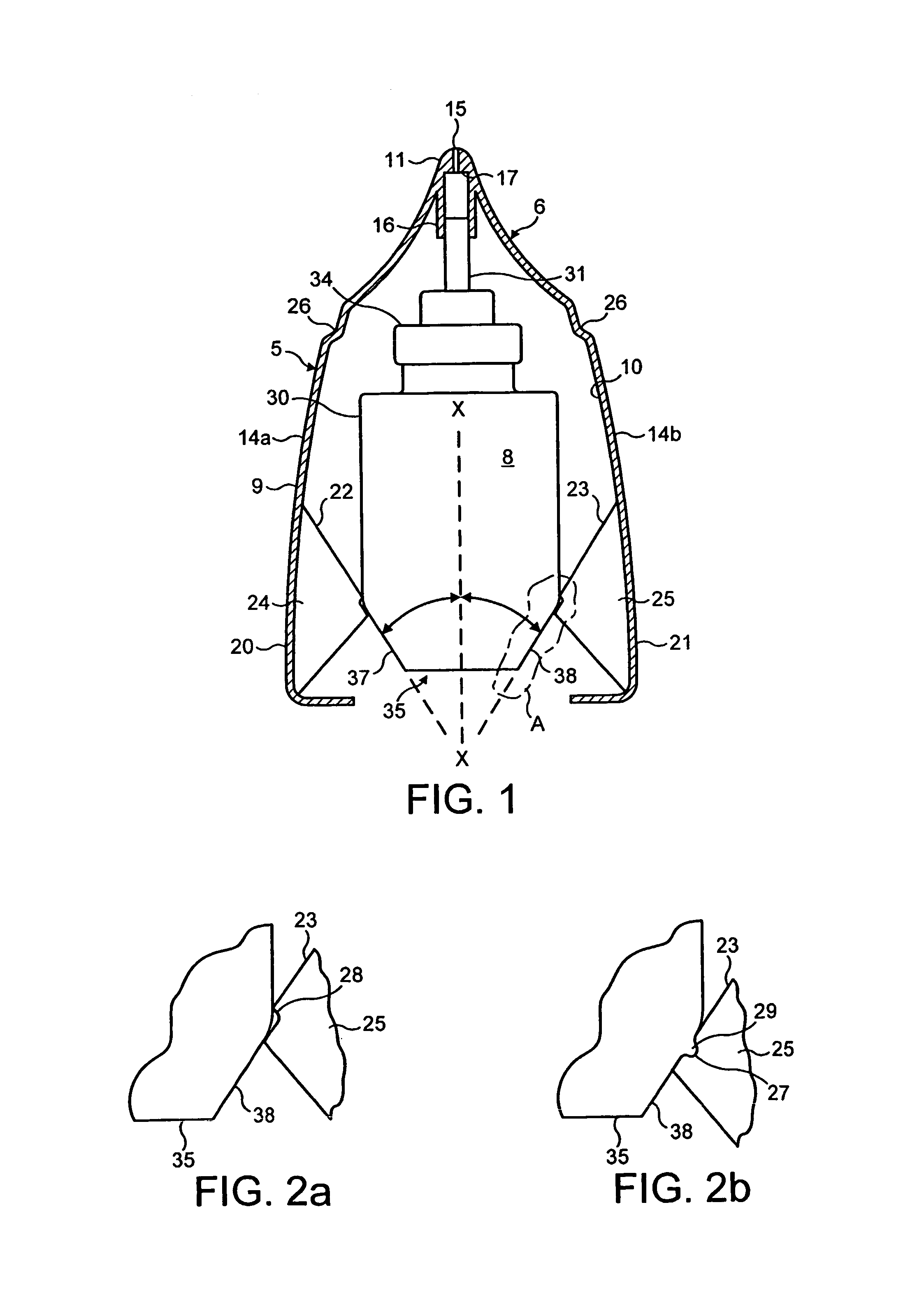
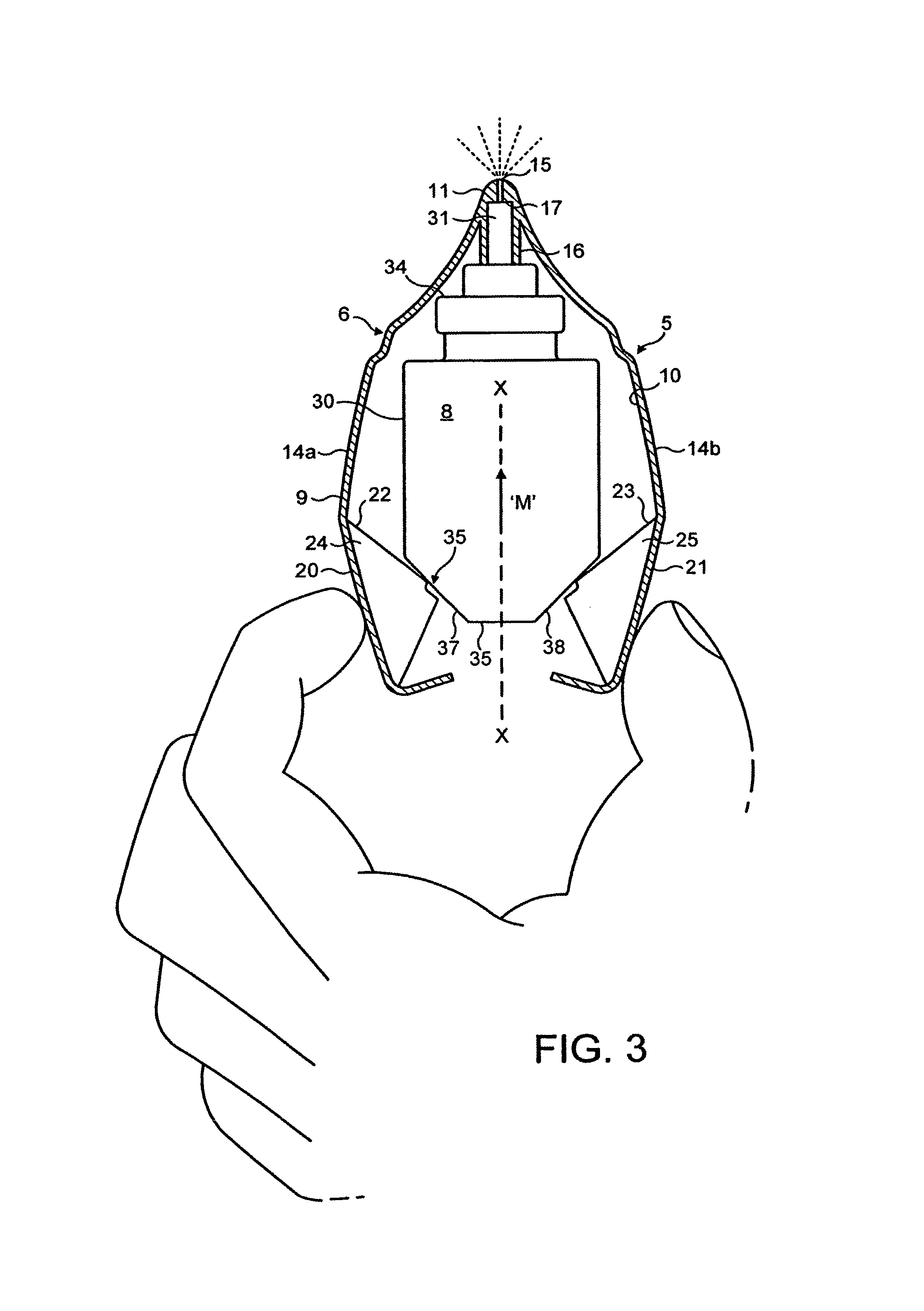
[0117]The primary difference between the fluid dispensing means shown in FIGS. 1 to 3 and that shown in FIGS. 4 and 5 is that the fluid dispensing device 5 in FIGS. 4 and 5 uses pre-load means in which the pre-load means 39, 40 is interposed between the housing 9 and the container 30.
[0118]The pre-load means comprises of two detents 39, 40 formed on the housing 9 for engagement with part of the container 30. The two detents 39, 40 are disengageable from the container 30 when the pre-determined force is applied to the finger operable means 20, 21 so as to allow the compression pump to be actuated.
[0119]Each of the detents is in the form of an arm 39, which extends downwardly from the housing 9 for engagement with a corner of the neck 34 of the container 30. A free end of each arm 39 has a step 40 formed therein, which prior to actuation is in abutting contact with the neck 34 of the container 30.
[0120]Operation of the fluid dispensing device is as follows.
[0121]From the position show...
third embodiment
[0127]The primary difference between the fluid dispensing means shown in FIGS. 1 to 3 and that shown in FIGS. 6 to 8 is that the fluid dispensing device 5 in FIGS. 6 to 8 uses pre-load means in which the pre-load means 41, 42, 43 is interposed between the container 30 and the discharge tube 31.
[0128]This embodiment has the advantage that it can be used irrespective of the mechanism used to actuate the pump.
[0129]The pre-load means comprises of a step 41 formed on the discharge tube 31 and two latching members in the form of arms 42 attached by a collar 43 to the neck 34 of the container 30. The step 41 is formed by a rib 44 extending circumferentially around the discharge tube 31 and positioned such that when the pump is actuated the rib 44 does not prevent travel of the discharge tube 31 into the container 30.
[0130]The arrangement is such that, when the pre-determined force is applied to the finger operable means in the form of the levers 20, 21, the latching members or arms 42 are...
fourth embodiment
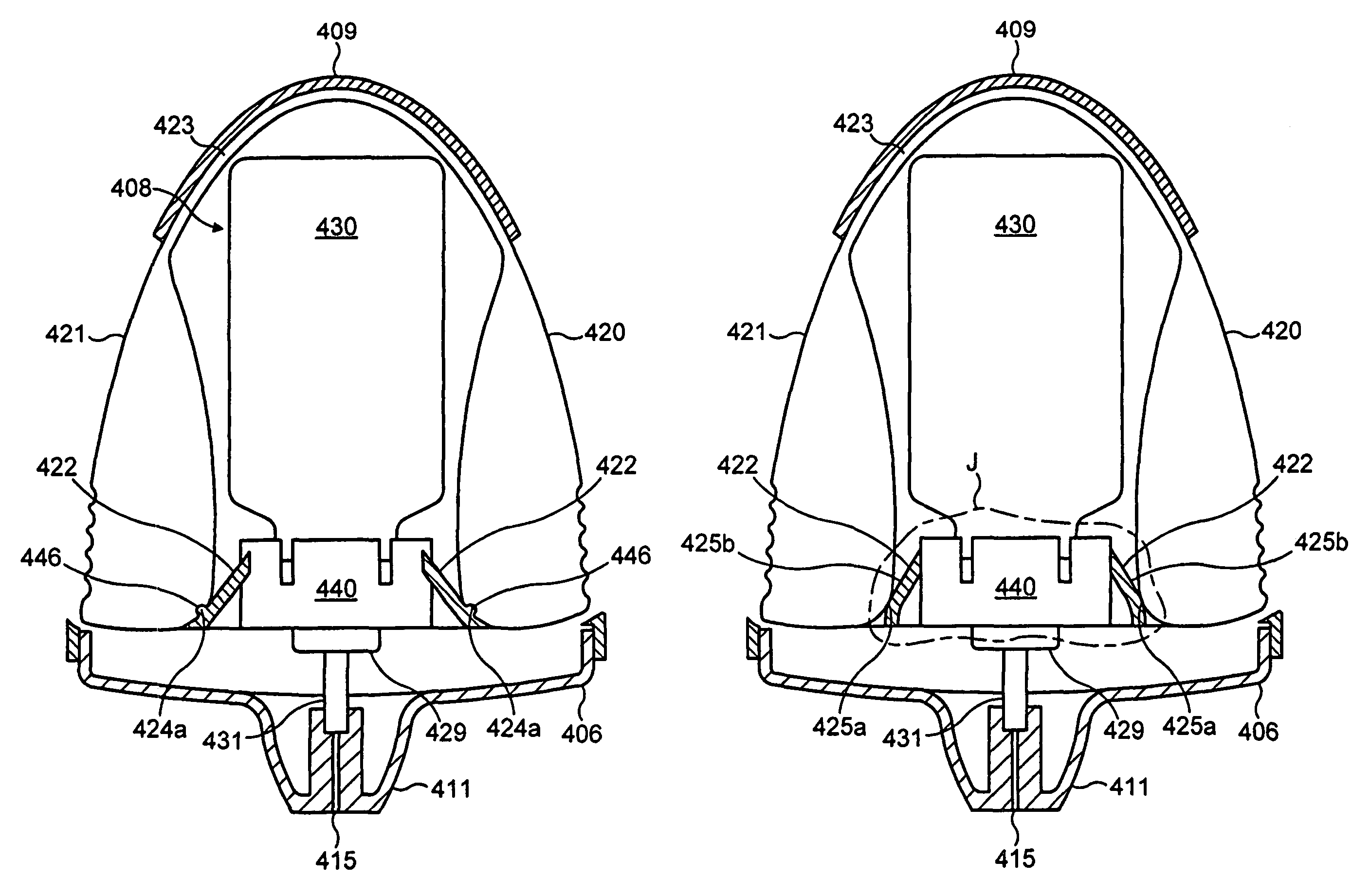
[0166]The fluid dispensing device 165 is fitted with a pre-load means in which the pre-load means 150, 152, 153 is interposed between the housing 109 and the lever 170.
[0167]The pre-load means comprises of a detent in the form of a tooth 150 formed on the housing 109 for engagement with the lever 170. The tooth 150 is formed at the end of an arm 152 formed as an integral part of the housing 109 and the lever 170 has a complementary rib 153 formed thereon for engagement with the tooth 150.
[0168]The detent or tooth 150 is disengageable from the rib 153 on the lever 170 when a pre-determined force is applied to the lever 170 so as to allow the compression pump to be actuated.
[0169]In more detail the fluid dispensing device 165 comprises of a body structure including the housing 109, the nozzle 111 extending out from an upper end of the housing 109 for insertion into a body cavity and a fluid discharge device 108 moveably housed within the housing 109.
[0170]The fluid discharge device 10...
PUM
 Abstract
Description
Claims
Application Information
 - R&D
- Intellectual Property
- Life Sciences
- Materials
- Tech Scout
- Unparalleled Data Quality
- Higher Quality Content
- 60% Fewer Hallucinations
Browse by: Latest US Patents, China's latest patents, Technical Efficacy Thesaurus, Application Domain, Technology Topic, Popular Technical Reports.
© 2025 PatSnap. All rights reserved.Legal|Privacy policy|Modern Slavery Act Transparency Statement|Sitemap|About US| Contact US: help@patsnap.com


