Method for protecting resonating sensors and open protected resonating sensors

a technology of resonating sensors and open protected resonating sensors, which is applied in the field of resonating sensors, can solve the problems of affecting the performance and accuracy of the sensor, the characteristics of the vibratable part of the sensor, and similar adverse effects on the performance of the sensor

Active Publication Date: 2005-12-29
MICROTECH MEDICAL TECH
View PDF41 Cites 28 Cited by
  • Summary
  • Abstract
  • Description
  • Claims
  • Application Information

AI Technical Summary

Benefits of technology

[0089] There is also provided, in accordance with an embodiment of the present invention, a method for protecting a resonating sensor unit h

Problems solved by technology

A common problem when resonating sensors such as, but not limited to, the sensors described above are implanted within a living body is the deposition of tissue or other materials of biological origin on the sensor or on parts thereof.
Such changes may adversely affect the sensor's performance and the accuracy of the determination of the physical variable which is to be determined.
Similarly, when a resonating sensor is disposed within a fluid or gas or other

Method used


Image

  • Method for protecting resonating sensors and open protected resonating sensors
  • Method for protecting resonating sensors and open protected resonating sensors
  • Method for protecting resonating sensors and open protected resonating sensors

Examples


experiment 1

[0251] Experiment 1

[0252] The experiment was performed using the multi-membrane passive ultrasonic pressure sensor 20 illustrated in FIGS. 2 and 3 of co-pending U.S. patent application Ser. No. 10 / 828,218 to Girmonski et al. The sensor was first placed on a slab of gelatin. The gelatin slab was prepared from a commercial food grade gelatin powder mixed with warm water (42% w / w) and cast to form a slab having a thickness height) of approximately six centimeters. The gelatin slab was placed in a controlled pressure chamber, and the sensor was positioned on top of the gelatin slab. The gelatin slab and the sensor were then covered with water and interrogated at various different pressure levels by an ultrasonic beam having a carrier frequency at 750 KHz and eleven sensor exciting frequencies of 72 KHz, 74 KHz, 76 KHz, 78 KHz, 80 KHz, 82 KHz, 84 KHz, 86 KHz, 88 KHz, 90 KHz and 92 KHz using the Doppler method disclosed by Girmonsky et al. in the above referenced co-pending U.S. patent ap...

experiment 2

[0254] Experiment 2

[0255] The experiment was performed using the multi-membrane passive ultrasonic pressure sensor 20 illustrated in FIGS. 2 and 3 of co-pending U.S. patent application Ser. No. 10 / 828,218 to Girmonski et al. The sensor was first placed in a controlled pressure chamber, covered with water and interrogated at various different pressure levels by an ultrasonic beam, as described for EXPERIMENT 1 above, to obtain a first measurement results data set and to determine the resonance frequency of the sensor at each known pressure level in the pressure chamber. The sensor was then taken out of the water and the upper part of the sensor (including the nine vibratable membranes of the sensor) was then covered with a thin layer of gelatin (42% w / w in water) prepared as disclosed in EXPERIMENT 1 above, by casting the warm gelatin solution on the upper surface of the sensor and letting the gel solidify. The thickness of the gelatin layer covering the upper part of the sensor and ...


PUM


Abstract

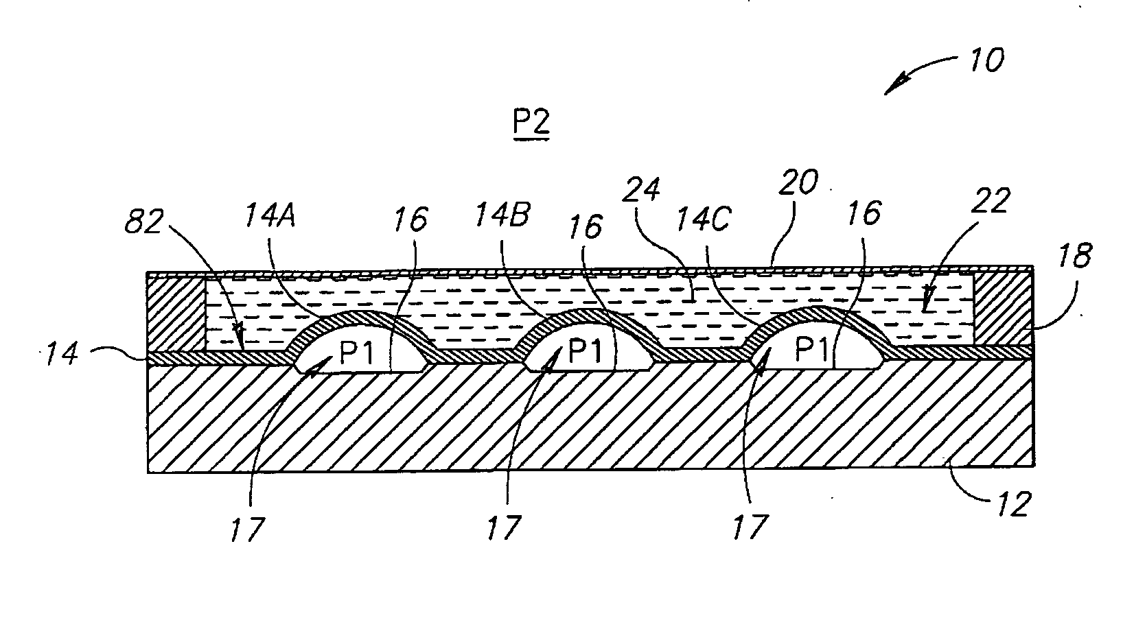
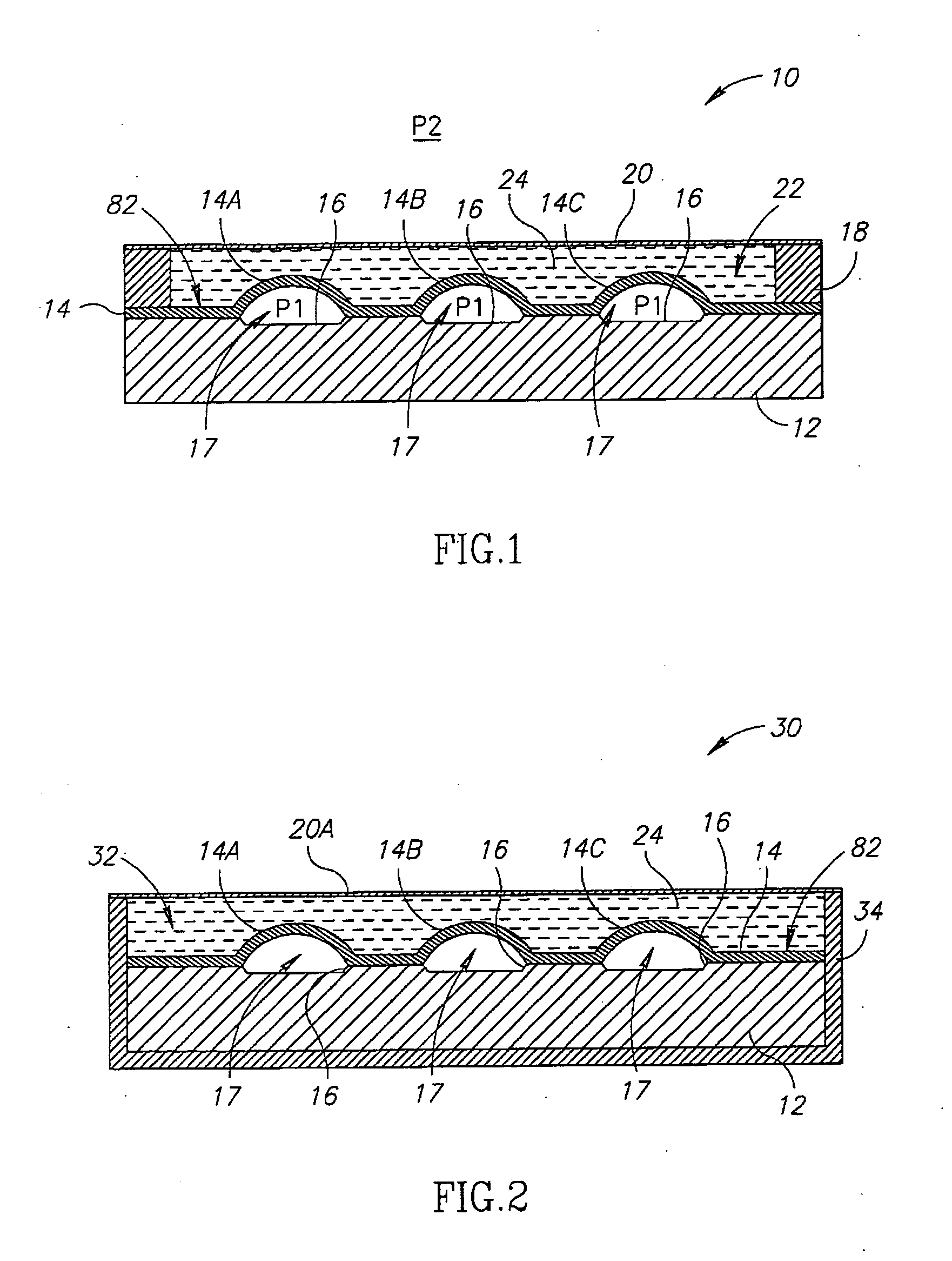
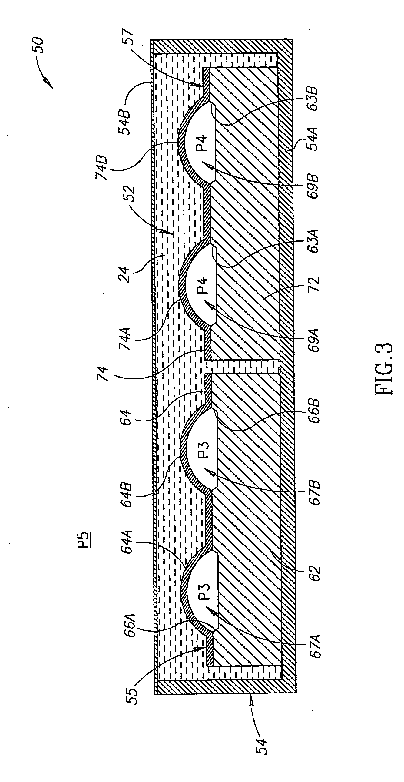
A protected resonating sensor may include at least one resonating sensor unit, each sensor unit has one or more vibratable members. The protected sensor includes at least one body of gel for protecting the vibratable member(s) of the sensor. The gel may be disposed on or attached to the sensor unit(s) covering the vibratable member(s) of the sensor unit(s). The gel may also be disposed in an open housing including one or more sensor units, and may cover vibratable members of different sensor units. The sensor unit may be any resonating sensor unit having a resonance frequency that depends on the value of a physical variable in a measurement environment. The protected sensor may also be attached to or included in or formed as part of any suitable device or sensor anchoring device and may also be implanted or inserted into a body or an organism. Methods are described for constructing the gel-protected sensor. The gel may have modified surface properties and may contain one or more drugs or therapeutic agents or other releasable substances. The gel may be formulated to retard or reduce diffusion of substances from the measurement environment into the gel and their deposition on the vibratable member(s).

Description

FIELD OF THE INVENTION [0001] The present invention relates generally to the field of resonating sensors in general and to methods for protecting resonating sensors from deposition of extraneous materials or tissues and protected resonating sensors in particular. BACKGROUND OF THE INVENTION [0002] Methods, devices and systems, using resonating sensors for determining the values of various physical parameters in a measurement environment are well known in the art. For example, methods systems and devices for using ultrasonically activated passive sensors for sensing and measuring the values of different physical parameters within a human body or in other environments and scientific and industrial applications, have been described. U.S. Pat. No. 5,619,997 to Kaplan, incorporated herein by reference in its entirety for all purposes, discloses a passive sensor system using ultrasonic energy. [0003] An ultrasonic activation and detection system ultrasonically activates passive sensors ha...

Claims


Application Information

Patent Timeline
IPC IPC(8): A61B5/00A61B5/03A61B8/00
CPCA61B5/00A61B5/6882A61B5/03
Inventor KAPLAN, SHAY
Owner MICROTECH MEDICAL TECH
Why Eureka
Try Eureka